You can configure pipe and structure styles so that pipes or structures that are drawn in section views use the actual position of where the sample line crosses the pipe or structure.
The following illustrations show the effect of these settings.
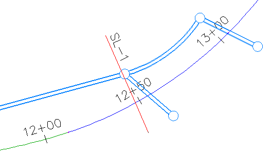
The following illustration shows the pipe network and the sample line crossing through a structure and a pipe.
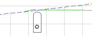
The following illustration shows the pipe network components displayed in a section view. In this illustration, the sliced solids options are not applied to the structure or pipe network style. Note that the structure is represented as if the sample line crosses it in the middle of the structure.
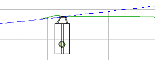
The following illustration shows the pipe network components with the sliced solids options applied. Note that the section more accurately represents the actual position of where the sample line crosses the structure.