Use this dialog box to view and change surface-related settings.
This topic documents settings in all surface-related Edit Settings dialog boxes (drawing-level, feature-level, and command-level).
- Drawing-level ambient settings are identified by the
 drawing icon.
- Surface feature settings are listed near the top of this dialog box, after the General property group, and are identified by the
 surface icon.
- Surface command settings are identified by the
 command icon.
For general information about drawing, feature, and command settings and their interaction, see About Autodesk Civil 3D Settings.
For information about drawing-level ambient settings, see Ambient Settings Tab (Drawing Settings Dialog Box).
Default Styles
Use these settings to specify the default styles assigned to surfaces and surface-related labels.
- Surface Default Style
-
Specifies the default surface style. Click in the Value column, and click
 to select a style in the
Surface Default Style dialog box.
to select a style in the
Surface Default Style dialog box.
- Marker Style
-
Specifies the default marker style. Click in the Value column, and click
to select a style in the
Marker Style dialog box.
- Surface Spot Elevation Label Style
-
Specifies the default spot elevation label style. Click in the Value column, and click
to select a style in the
Surface Spot Elevation Label Style dialog box.
- Surface Slope Label Style
-
Specifies the default slope label style. Click in the Value column, and click
to select a style in the
Surface Slope Label Style dialog box.
- Render Material
-
Specifies the default render material. Click in the Value column, and click
to select a render material in the Render Material dialog box.
Default Name Format
Use this setting to specify the default name format for new surfaces. Click in the
Value column, and click
![]() to make changes in the
Name Template dialog box.
to make changes in the
Name Template dialog box.
Contour Labeling Defaults
Use these settings to specify the defaults assigned to surface labels.
- Display Contour Label Line
-
Specifies whether or not the contour label lines are displayed.
- Surface Contour Label Style Major
-
Specifies the default major contour label style. Click in the Value column, and click
to select a style in the
Surface Contour Label Style Major dialog box.
- Surface Contour Label Style Minor
-
Specifies the default minor contour label style. Click in the Value column, and click
to select a style in the
Surface Contour Label Style Minor dialog box.
- Surface Contour Label Style User-defined
-
Specifies the default user-defined contour label style. Click in the Value column, and click
to select a style in the
Surface Contour Label Style User-defined dialog box.
Surface Defaults
- Default Rebuild -Automatic
-
Specifies Automatic as the default setting for the Rebuild Surface command.
Add Contour Labeling
Use this setting to specify the defaults assigned to surface labels.
- Interval Along Contour
-
Specifies the default distance between labels along the contour. Enter a value or click
 to graphically select a distance in the drawing area.
Import Options
Use these settings to specify the defaults assigned when creating surfaces.
- Use Custom Null Elevation
-
Specifies whether a custom null elevation is used when importing a surface from a DEM file.
- Null Elevation
-
Specifies the default custom null elevation used when importing a surface from a DEM file.
Surface Creation
- Surface Default Type
-
Specifies the default surface type that is used when creating a surface. For more information, see About Creating Surfaces.
- Surface Name Template
- Specifies the name template to use when creating new surfaces. For more information, see Name Template dialog box.
- Cut Factor
- Specifies the cut factor to apply to the volume calculations. As the volume of material generally expands after it is removed, the cut factor is usually set to greater than 1.0, indicating swell or expansion. For example, a 1.2 cut factor would mean that for every 1.0 cubic meter of material removed, 1.2 cubic meters of volume would need to be accounted for transport.
- Fill Factor
- Specifies the fill factor to apply to the volume calculations. As the material generally compacts when used as fill, the fill factor is usually set to greater than 1.0, to indicate compaction or shrinkage of the material when it is used as fill. For example, a 1.2 fill factor would mean that for every 1.0 cubic meter of material required for the fill site, 1.2 cubic meters of that material would need to be transported. For example, for a material that compacts to 93% of its original value when used as fill, enter 1.075 (which is derived by dividing 1.0 by .93) as the fill factor to compensate for the extra material that must be added.
- Grid Surface X-Spacing
-
Specifies the default value for a grid surface's X spacing.
- Grid Surface Y-Spacing
-
Specifies the default value for a grid surface's Y spacing.
- Grid Surface Orientation
-
Specifies the default orientation for a grid. Enter a value or click
to graphically select an orientation in the drawing area.
- Store Referenced Surface In Drawing
- Specifies whether to store the geometry of reference surfaces in the drawing. If you choose to save the reference surface geometry in the drawing, the drawing that contains the reference will become larger, but will open more quickly unless the source surface has changed. For more information, see To Work With Surface References.
- Drawing for New Surface
- Specifies the default setting for the target drawing when creating cropped surfaces.
Volume Surface Creation
Use these settings to specify the defaults assigned when creating volume surfaces from the Volumes Dashboard.
- Volume Surface Default Type
-
Specifies the default volume surface type that is used when creating a volume surface. For more information, About Creating Surfaces.
- Volume Surface Name Template
- Specifies the name template to use when creating new volume surfaces. For more information, see Name Template dialog box.
- Cut Factor
- Specifies the cut factor to apply to the volume calculations. As the volume of material generally expands after it is removed, the cut factor is usually set to greater than 1.0, indicating swell or expansion. For example, a 1.2 cut factor would mean that for every 1.0 cubic meter of material removed, 1.2 cubic meters of volume would need to be accounted for transport.
- Fill Factor
- Specifies the fill factor to apply to the volume calculations. As the material generally compacts when used as fill, the fill factor is usually set to greater than 1.0, to indicate compaction or shrinkage of the material when it is used as fill. For example, a 1.2 fill factor would mean that for every 1.0 cubic meter of material required for the fill site, 1.2 cubic meters of that material would need to be transported. For example, for a material that compacts to 93% of its original value when used as fill, enter 1.075 (which is derived by dividing 1.0 by .93) as the fill factor to compensate for the extra material that must be added.
- Grid Surface X-Spacing
-
Specifies the default value for a grid surface's X spacing.
- Grid Surface Y-Spacing
-
Specifies the default value for a grid surface's Y spacing.
- Grid Surface Orientation
-
Specifies the default orientation for a grid. Enter a value or click
to graphically select an orientation in the drawing area.
Build Options
Use these settings to specify the build options assigned when creating surfaces.
- Copy Deleted Dependent Objects
-
Specifies whether a drawing object is copied to the surface definition item if the object is deleted.
- Exclude Elevations Less Than
-
Specifies whether an elevation less than a certain value should be excluded when the surface is built.
- Elevation <
-
Specifies the elevations to exclude when the Exclude Elevations Less Than property is set to Yes. Enter a value or click
to select an elevation in the drawing area.
- Exclude Elevations Greater Than
-
Specifies whether an elevation greater than a certain value should be excluded when the surface is built.
- Elevation >
-
Specifies the elevations to exclude when the Exclude Elevations Greater Than property is set to Yes. Enter a value or click
to select an elevation in the drawing area.
- Use Maximum Angle
-
Specifies whether the triangles on the exterior border of the TIN will be assessed to see if they exceed the Maximum Angle Between Adjacent TIN Lines (CreateSurface and VolumesDashboard command settings only). If Use Maximum Angle is set to Yes, triangles on the exterior border of the TIN are assessed. A triangle is removed from the TIN if the angle which faces to the border edge exceeds the maximum angle specified.
The following illustrations show examples of the effect of the Use Maximum Angle setting.
- If the
Maximum Angle Between Adjacent TIN Lines setting is set to 130 degrees, the highlighted triangles in the following illustration would be removed.

- If the
Maximum Angle Between Adjacent TIN Lines setting is set to 140 degrees, the highlighted triangles in the following illustration would be removed.
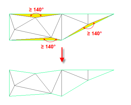
This process is iterative so that when a triangle is removed, exposing one or two new border edges, the new border triangles are tested and removed according to the same criterion. This operation assesses triangles that border exterior boundaries. Triangles on interior boundaries are not affected by this operation.
- If the
Maximum Angle Between Adjacent TIN Lines setting is set to 130 degrees, the highlighted triangles in the following illustration would be removed.
- Maximum Angle Between Adjacent TIN Lines
- Specifies the maximum angle to use for the Use Maximum Angle option (CreateSurface and VolumesDashboard command settings only). A triangle is removed from the TIN if the angle which faces to the border edge exceeds the maximum angle specified.
- Use Maximum Triangle Side Length
-
Specifies whether the surface triangles that exceed the length specified by the Maximum Triangle Length property are removed from the boundary of the surface (CreateSurface and VolumesDashboard command settings only).
- Maximum Triangle Length
-
Specifies the triangle length to use when the Use Maximum Triangle Length property is set to Yes. Enter a value or click
to select a length in the drawing area (CreateSurface and
VolumesDashboard command settings only).
- Convert Proximity Breaklines to Standard
-
Specifies whether proximity breaklines are converted to standard breaklines when the surface is built (CreateSurface and VolumesDashboard command settings only).
- Allow Crossing Breaklines
-
Specifies whether breaklines can cross each other (CreateSurface and VolumesDashboard command settings only).
- Elevation To Use
-
Specifies the elevation to use for the crossing breaklines (CreateSurface and VolumesDashboard command settings only):
- Use First Breakline Elevation At Intersection: Uses the first breakline elevation to determine the elevation at the intersection.
- Use Last Breakline Elevation At Intersection: Uses the last breakline elevation to determine the elevation at the intersection.
- Use Average Elevation At Intersection: Uses the average of the first and last breakline to determine the elevation at the intersection.
For more information on these settings, see the Build properties in Definition Tab (Surface Properties Dialog Box).
Bounded Volume Creation
- Default Mid-Ordinate Distance
- Specifies the mid-ordinate distance for the boundary's breaklines, which is used to tessellate the polyline arcs from which the boundary is being created.
Dynamic Highlight Options
- Surface Border Color
- Specifies the color to use to outline volume surfaces in the drawing when they are selected in the Volumes Dashboard.
- Surface Border Lineweight
- Specifies the lineweight to use to outline volume surfaces in the drawing when they are selected in the Volumes Dashboard.
- Boundary Polygon Color
- Specifies the color to use to outline bounded areas in the drawing when they are selected in the Volumes Dashboard.
- Boundary Polygon Lineweight
- Specifies the lineweight to use to outline bounded areas in the drawing when they are selected in the Volumes Dashboard.
Water Drop Path
Use these settings to specify default water drop path options for surfaces.
- Path Layer
-
Specifies the default layer on which to draw the water drop path. Click in the Value column, and click
to select a type of path in the
Path Layer dialog box.
- Path Object Type
-
Specifies the default type of AutoCAD object to use for the water drop path. Either 2D Polyline or 3D Polyline.
Water Drop Marker
Use these settings to specify default water drop marker options for surfaces.
- Place Marker At Start Point
-
Specifies whether to draw a marker at the start point of the water drop path.
- Start Point Marker Style
-
Specifies the default start point marker style. Click in the Value column, and click
to select a style in the
Start Point Marker Style dialog box.
SimplifySurface
Use these settings to specify default options for simplifying surfaces.
- Simplify Method
-
Specifies the default method by which surfaces will be simplified:
- Edge Contraction: Contracts triangle edges to single points.
- Point Removal: Selects and removes surface points.
- Region Options
-
Specifies the default method by which surfaces will be simplified:
- Use Existing Surface Border: You specify the existing surface border as the boundary of the surface simplification region.
- Specify Window/Polygon: You specify the surface simplification region within a drawn rectangle.
- Select Objects: You specify one of either 2D or 3D polylines, parcels, circles, feature lines, or survey figures.
- Use Percentage Of Points To Remove
-
Specifies whether simplify the image by removing a percent of surface points.
- Percentage Of Points To Remove
-
Specifies the percent of surface points to remove.
- Use Maximum Change In Elevation
-
Specifies whether you will set a default maximum change in elevation.
- Maximum Change In Elevation
-
Specifies the maximum allowed difference between the elevation of the original surface and the elevation of the simplified surface.
For more information about simplifying surfaces, see Simplify Surface Wizard.
Export Options
Use these settings to specify the defaults assigned when exporting surfaces to a DEM file.
- Use Custom Null Elevation
-
Specifies whether a custom null elevation is used when exporting to a DEM file.
- Null Elevation
-
Specifies the default custom null elevation used when exporting to a DEM file.
- Grid Spacing
-
Specifies the spacing between grids when exporting to a DEM file.
Add Data Options
Use these settings to specify the defaults assigned when adding contours, boundaries, and breaklines to a surface.
- Default Weeding Distance
-
Specifies the default weeding distance.
- Default Weeding Angle
-
Specifies the default weeding angle.
- Default Supplementing Distance
-
Specifies the default supplementing distance.
- Default Mid-ordinate Distance
-
Specifies the default mid-ordinate distance.
- Default Boundary Type
-
Specifies the default boundary type.
- Default Non-destructive Setting
-
Specifies the default selection of a type of breakline (destructive of non-destructive).