Use grips to manually edit pipe runs in plan view.
When you use grips to move a pressure network part near another part’s open connection, a glyph
 appears near the cursor when two parts are close enough to be connected. Releasing your cursor when this glyph is displayed connects the two pressure network parts. This behavior applies for any two parts of any type, as long as the two parts are in the same pressure network.
In the following descriptions, remember that adjusting pipe runs with grips does not prevent you from editing the angle of a pipe beyond the allowable deflection. Pipes which have exceeded the allowable deflection can be detected by running the Run Design Check command.
The grips described in the following sections are highlighted in each illustration in red.
End Point: Lengthen
These grips enable you to shorten or lengthen a pressure pipe from one free end. The direction of the pipe being lengthened or shortened remains the same whether it is connected to another pressure pipe, fitting, or appurtenance.
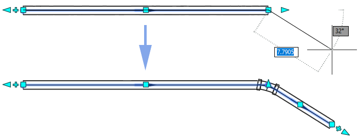
End Point: Deflection (Straight Pipes)
These grips enable you to change the angle of the free end of a pressure pipe. The angle is measured from the centerline of the pipe. When this grip is selected you can move the pipe or enter an angle of deflection to apply. When moving them in the direction of the pipe, the pipe will extend as it does with the Lengthen grips.

The following illustration shows a selected deflection grip and the visual cues of deflection the pipe can be moved.
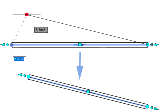
Connected pipes in a pipe run will also move and adjust their points of intersection to accommodate the new pipe geometry.
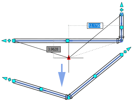
Midpoint: Move (Straight Pipes)
These grips enable you to move the pressure pipe to a new location. The direction and length of the pipe remain the same.

Connected pipes in a pipe run will also move and adjust their points of intersection to accommodate the new pipe location.
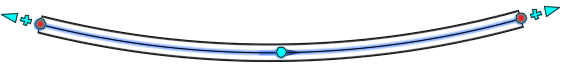
End Point: Deflection (Curved Pipes)
Much like the deflection grips of the straight pipe, these grips move the end point and change the geometry of the curve. The angle is measured from the centerline of the pipe. When this grip is selected you can move the pipe or enter an angle of deflection to apply.
The following illustration shows a selected deflection grip and the visual cues as the grip is moved.
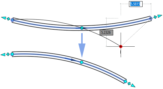
Connected pipes in a pipe run will also move and adjust their points of intersection to accommodate the new curved pipe geometry.
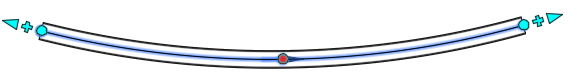
Midpoint: Radius (Curved Pipes)
These grips enable you to adjust the radius of the curved pipe.
The following illustration shows a selected radius grip and the visual cues of the curved pipe geometry as the radius is adjusted.
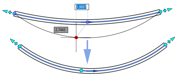
Connected pipes in a pipe run will also move and adjust their points of intersection to accommodate the new curved pipe geometry.
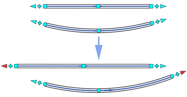
End Point: Continue Layout
These grips enable you to continue laying out a pipe run by adding pressure pipes. These grips appear on open pressure pipe connections, for both straight and curved pipes.

You can use these grips to continue to draw pipe runs in your drawing.
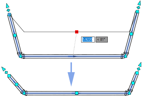
Point of Intersection
The points of intersection along a pipe run represent where pipes join and bend. They also act as grips to adjust your pipe run.
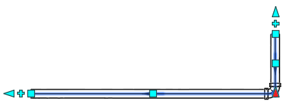
As grips, they work much in the same way as the end point deflection grips on open ended pipes. The two pipes at the intersection will change their length and locations (straight pipes) or their curve geometry will adjust to meet their new locations (curved pipes).