Refer to the following topic for tips about working with surfaces.
Surface Tracking for Animated Vehicles
One of the most popular features in Civil View is the ability to use intelligent relationships between animated vehicles and underlying road surfaces to help make sure that vehicles always cling to the surface of the road. Vehicles even react to any changes to the underlying road surface (for instance after a design change). This feature is known as surface tracking.
One of the downsides to using surface tracking is that it can have a detrimental effect on viewport performance. This problem can be exacerbated by the use of complex terrain surfaces and high numbers of vehicles. This is because when you playback animation in a 3ds Max viewport, these relationships have to be re-calculated for every vehicle at every frame of the animation.
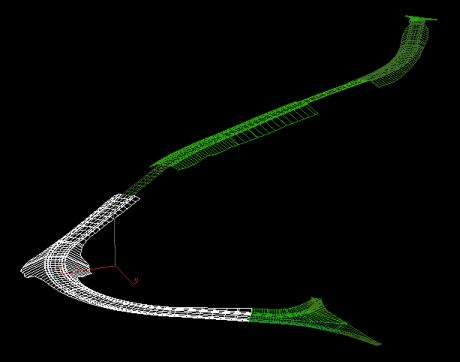
Another consideration specific to Autodesk Civil 3D-derived projects is that the Export to Civil View for 3ds Max command generates separate corridor surfaces for each corridor region. Only one of these surfaces may be nominated as the parent surface for each animated vehicle (see illustration below).
Improving Efficiency of Surface Tracking by Using a Subassembly Link Corridor Surface
The performance of surface tracking has a direct relationship with the number of faces/triangles on the nominated parent surface. For each frame of animation, Civil View searches through every face of a parent surface until it finds the one that a vehicle is sitting on. Only then can it calculate the height and slope of the road surface that needs to be applied to the vehicle at that moment of time.
For best performance of surface tracking, use a parent surface which contains the fewest number of triangles/faces as possible, preferably just the triangles that each vehicle will encounter in the animation.
It is not generally necessary to manually create corridor surfaces in Autodesk Civil 3D. The Export to Civil View for 3ds Max command generates its own corridor surfaces during the export process using a user-specified link code filter. However, there are some instances where traditional Autodesk Civil 3D corridor surfaces can be useful.
In Autodesk Civil 3D, surfaces can be generated from corridors using a range of criteria. You can decide which subassembly link codes should be used to form the extent of the corridor surface geometry. This opens the possibility to generate a surface in Autodesk Civil 3D purely for surface tracking purposes in Civil View, based on just the subassembly links (see illustration below).

Upon import into Civil View, this surface may then be hidden so that it is not visible in rendered output or in the viewports.
Because traditional corridor surfaces in Autodesk Civil 3D are generated for the entire length of the corridor (including all corridor regions) this also solves the per-region surface problem described above.
Using this approach, although all vehicles will be tracking a different surface to the one that you see in any rendered output, any design changes to the corridor in Autodesk Civil 3D will cause all related surfaces to be updated in Civil View, including this dedicated hidden surface for vehicle surface tracking.