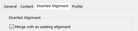
When you create a turnout, you can use an option on the Diverted Alignment tab of the Create Turnout dialog box to merge the turnout's diverted alignment with an existing alignment.
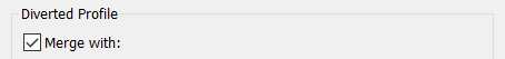
Likewise, on the Profile tab, you can select an option to merge the diverted alignment's profile with an existing profile.
You may need to manually connect the entities of the turnout and the merged alignment and profile after the turnout is created by drawing additional alignment and profile entities. You can do this by using the alignment and profile editing commands.
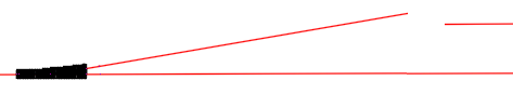
For example, when you create the turnout the entities may appear as follows in plan view, where the diverted alignment extends from the turnout on the left, and the alignment it's merged with is on the upper right:
You can use the alignment editing commands to connect the two as shown in the following example:

To connect a diverted alignment
- When creating a turnout, on the Diverted Alignment tab, select the Merge with an Existing Alignment check box and specify the alignment to merge with.
- After the turnout is created, in the drawing, click the diverted alignment, right-click to display the context menu, and click Edit Alignment Geometry.
- In the Alignment Layout Tools, select an alignment editing command such as Free Curve Fillet.
- Select the diverted alignment, then select the merged alignment, and then enter a fillet radius.
To connect a diverted profile
You can connect a turnout's diverted profile with its merged profile using a similar workflow, except you select the diverted profile in the profile view, right-click, and select the Edit Profile Geometry command.
For example, when you follow the steps above, the turnout entities may appear in profile view as follows, where the diverted profile is on the left, and the profile of the alignment its merged with is on the right:

After connecting the entities with a free vertical curve, the profile appears as follows:

- Follow the steps above to connect the diverted alignment to the merged alignment.
- In the profile view for the merged alignment, select the profile of the diverted alignment.
- Right-click to display the context menu and click Edit Profile Geometry.
- Select an editing command such as Free Vertical Curve (Circular).
- Select the profile of the diverted alignment and then select the profile of the merged alignment, and then enter a radius.