The Extract Corridor Solids command provides functionality that allows you to extract AutoCAD solids or bodies from Autodesk Civil 3D corridor model shapes and links.
These generic AutoCAD entities can then be used for analysis and visualization or with other applications that are unable to directly interact with the Autodesk Civil 3D corridor model.
Extracting Solids or Bodies
When using the Extract Corridor Solids command, you can choose to extract several types of AutoCAD entities. The types of AutoCAD entities include:
- AutoCAD 3D Bodies
- When opting to create AutoCAD 3D Bodies, the program creates shapes and links that match the way the corridor is constructed. AutoCAD bodies are displayed much like AutoCAD solids. However, there are some limitations in the way AutoCAD bodies can be used with other applications or within AutoCAD. For example, the MASSPROP command only works with AutoCAD solids.
Note: Links are always exported as bodies rather than solids (regardless of the object type you choose to create).Note: Choosing to extract either type of AutoCAD solid offers more benefits than extracting AutoCAD bodies. For example, solids let you graphically represent the mass of subassemblies which is unsupported by AutoCAD bodies. This gives you the option to extract mass properties, such as volume.
- AutoCAD 3D Solids
- When you create AutoCAD 3D Solids, the program also creates shapes and links that match the way the corridor is constructed. AutoCAD solids can be used to graphically represent the mass of a subassembly shape and can be used to extract mass properties, such as volume. Solids are also more generally accepted by other solid modeling applications, unlike AutoCAD bodies.
Note: Extracting AutoCAD solids works best if you plan to use another solid modeling application to further refine the model.
- AutoCAD 3D Solids (Swept Solids)
- The Swept Solids option creates objects that are swept along points in the corridor. The result is smoothed solid objects that lack tessellation at corridor sampling points. This method may result in solids that do not accurately represent your corridor.
Note: Processing swept solids can take additional time when compared to the standard solid or body creation options.
Selecting Corridor Regions and Ranges for Export to Solids or Bodies
You can export corridor solids or bodies based on an entire corridor region, one or more station ranges for a baseline, or for everything within a selected polygon. The most appropriate option is dependent upon the intended use of the extracted model data.
- By Regions
- The By Regions option is used to create solids for specified regions. All shapes and links in within the region are included.
- All Regions
- The All Regions option is used to create solids for the entire corridor. All shapes and links in all corridor baselines are included. This is the fastest solution if you need a quick solid representation of the entire corridor.
- Station Range
- Use this option to create solids along a specific corridor baseline based on a start/end station range. This range is specified by entering station values or by graphically selecting station locations.
- Within Polygon
- The Within Polygon option allows you to create solids from all shapes and links within a selected closed polygon. All corridor modeling baselines are included. This option is ideal for areas such as roadway intersections that are constructed from numerous corridor baselines.
Controlling Layers and Colors of Corridor Solids or Bodies
It is very important to consider how corridor solids are going to be used when defining the layer name and object appearance. For example, if using the solids for construction staging, it is beneficial to include information such as construction region or station range in the layer name.
You can control the layers and colors in the following ways:
- Layer Name Template
- The Layer Name Template is used to define the information that gets used when creating AutoCAD layers. Template options include:
- User Defined Text — Any user defined text that is needed in a layer name.
- Construction Region Start Station — The starting station value of the corridor solids region.
- Construction Region End Station — The ending station value of the corridor solids region.
- Construction Region Name — The region name is automatically formatted as “Region: XX+XX – XX+XX” and is calculated by the baseline station values. You can change the default name by selecting the name in the list.
- Corridor Name — The name of the corridor.
-
Codes
— The link code name or shape code name that is derived from the subassembly definition.
Note: The Link Code and Shape Code names are valuable for accessing the exported model to determine its intent, for example, Base, Sub-base, Pave1, etc.
- Subassembly Name — The subassembly name can be included in the layer name, if needed. In most cases, the Shape Code from subassemblies provides the necessary information for those accessing the exported model. However, there may be cases, such as reviewing the design, where the subassembly name could be valuable.
- Subassembly Shape Index — The subassembly shape index name can also be included.
- Subassembly Side — The subassembly side can be included to identify the side of the baseline (left, right, or no).
- ExportCorridorToSolids setting
- This command setting is accessed from the Settings tab of the Toolspace under Corridor
 Commands. Use it to help set up a layer name template. This setting is saved with the current drawing or it can be added to a drawing template so that everyone has consistent corridor solid naming.
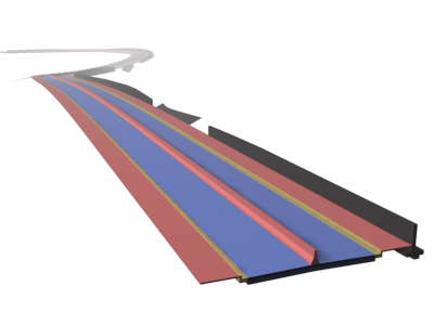
- Color
- Colors are automatically set to match the shape or link style (model view direction) that is currently set for the corridor. The corridor uses a code set style to control the appearance of the corridor in plan, model, and section views. The corridor solids color is driven by the shape and link styles for the corridor.