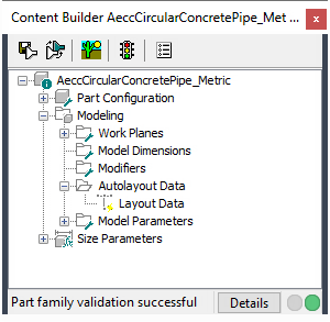
Use the Autolayout Data option to define the part placement point in the drawing.
After finalizing the part model, you need to define the placement point for the part to ensure that it can be placed correctly in a drawing. The Autolayout Data option in the part browser controls how placement points can be defined. When you enable this option, an Autolayout Data folder is available in the part browser that includes commands for adding placement points.
This is done by selecting a fixed point in the model. This point must be in the z = 0 plane. By choosing a fixed point, the parametric model will retain this position as it is dynamically sized.

The placement point is the insertion point used to place the part in a drawing. You simply specify a point in your model for the placement point.