Mesh the Part
Create the mesh for the part geometry.
In meshing the composite plate, a global seed size of 0.075 is used to ensure the mesh is fine enough to capture the location and propagation of failure, but coarse enough to allow for a moderate solution time. Manual edge seeding is used to ensure there is a single element in the thickness direction and the area concatenation tool is allows for a mapped mesh around the hole.
From the menu at the top of the GUI, click Select > Entities. In the dialog box that appears, select Volumes from the drop-down list and select the Reselect radio button. Click OK.
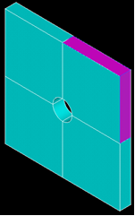
Select the 4 volumes that surround the hole and click OK.
From the top menu, click Plot > Replot. The 4 volumes that surround the hole should be the only volumes displayed.
To use the mapped mesh algorithm, the volume must be defined by 6 areas. Since each of the 4 volumes that surround the hole is defined by 7 areas, two areas per volume must be concatenated.
Click Main Menu > Preprocessor > Meshing > Concatenate > Areas.
For each of the 4 volumes, select the two areas as shown in below and click the Apply button.
Do not select all 8 areas and then click the Apply button. Simply select the two appropriate areas per volume and click the Apply button.
Since a single element will be used to define the entire 24 ply layup, manual seeds must be specified on the lines parallel to the global Z-direction.
From the top menu, click Select > Everything. Then click Plot > Replot.
Click Preprocessor > Meshing > Size Cntrls > ManualSize > Lines > Picked Lines.
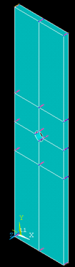
Select all of the lines parallel to the global Z-direction as shown below. Click OK.
In the dialog box that appears, enter a value of 1 in the NDIV entry box. Click OK.
Click Preprocessor > Meshing > MeshTool.
In the dialog box that appears, click the Set button next to the Global option under Size Controls, enter 0.075 in the SIZE entry box, and click OK.
Select the Hex and Mapped radio buttons and click the Mesh button.
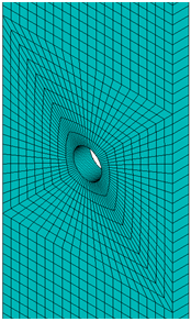
Select all 8 volumes from the Graphics Window and click OK. The part is now meshed and should be similar to the mesh shown below.
Since a mapped mesh was used, the element normals may be inconsistent. To reorient the element normals, select Preprocessor > Modeling > Move/Modify > Elements > Orient Normal. Select Positive z-axis from the DIR list and click OK.