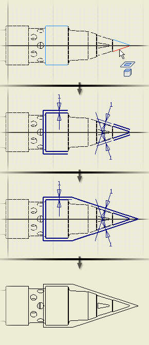
Guidelines and procedure for creating a sketch associated with a model view.
The following image shows how model geometry can be projected into a sketch. In this particular example, the projected geometry is used to help define sketched lines.

Projected geometry remains associated to the parent geometry. If you change the geometry in the model, the projected geometry updates when the drawing is updated.
You can use projected geometry just like any other geometry in a drawing sketch.
For example, you can:
- Project some geometry from a view, add geometry to create a closed boundary, and then add hatch or color fill.
- Project geometry and use it to define a rectangular or circular pattern.
- Project geometry to define the boundary for a breakout.
Follow these guidelines for projected geometry:
- Only the geometry in the view associated to the sketch can be projected.
- Hidden lines cannot be projected to a sketch.
- Projected lines assume the color, line weight, and other attributes of the active line style.
- If you scale the drawing view, the sketch geometry scales relative to the view.
- When you change the model, the projected geometry in the drawing updates when the drawing updates. If you delete geometry in the model, the projected geometry in the drawing is deleted as well.
- If you make topology changes, such as adding fillets or chamfers, the related geometry is deleted from the projected geometry in the drawing sketch.
- You cannot project thread representations to a drawing sketch.
Create a sketch attached to a drawing view
- On the ribbon, click
Sketch tab
 Create Panel
 Project Geometry
 .
.
- Select the geometry to project.
- Right-click, and then select Done [ESC] to project the selected geometry to the sketch.
Tip: On the Quick Access toolbar, click the arrow next to Select and change the filter to Select Part to select all geometry in a part in the view.