You can add, edit, show, and delete dimensions; you can also specify how dimensions appear.
If you are new to Inventor we recommend looking over the Getting Started and Guided Tutorials that pertain to sketches.
Brief video of creating sketch dimensions
Add Dimensions
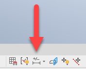
- In a sketch, click
Sketch tab
 Constrain panel
Dimension
Constrain panel
Dimension
 (2D sketch) or
3D Sketch tab
Constrain panel
Dimension
(3D sketch).
(2D sketch) or
3D Sketch tab
Constrain panel
Dimension
(3D sketch).
- In the graphics window, click the geometry that you want to dimension and then click to place the dimension.
In a 3D sketch, the dimension text is parallel to a plane created by the two selections.
- Continue selecting geometry to create additional dimensions, or right-click and choose OK.
In a 3D sketch, you can enable or disable adding dimensions to geometry as you sketch. Click Dynamic Dimension in the status bar to enable or disable the ability to add dimensions in the value box as you sketch. You can also press Ctrl + D to toggle Dynamic Dimension on or off.
Edit Dimensions
- In a sketch, to edit a dimension do either of the following:
- Double-click the dimension you want to edit.
- Click the Dimension command in the Constrain panel and then click the dimension you want to edit.
- In the Edit Dimension dialog box, do any of the following:
- Enter a new value in the dimension field.
- Click the arrow, choose Measure, and then click the geometric element whose measurement you want to use.
- Click the arrow, choose Show Dimensions, in the browser click the feature having the dimension you want to use, the feature dimensions display. Click the dimension you want to use.
- Click the arrow and choose a value from the list.
Note: You can also enter or edit an expression that defines a parameter. For example, enter HGHT = 5mm. The expression is parsed to create the parameter HGHT and assigns the value of 5 mm. - Click the check mark to accept the new dimension.
- To reposition dimension text, pause the cursor over the text, when you see the move cursor
 , click-drag the dimension to a new position.
Delete Dimensions
- Select the dimension in the graphics window and press Delete, or right-click and choose Delete.
Show/Hide Dimensions
Make dimensions visible so you can edit them.
- Right-click a feature in the browser or graphics window and choose Show Dimensions.
- Right-click a sketch in the browser and toggle on Dimension Visibility.
- Select View Tab, Visibility panel, Object Visibility, and select or deselect the Sketch Dimensions check box to show or hide all sketch dimensions.
Note: When the Sketch Dimensions option is deselected, it overrides the individual sketch dimension visibility set in the context menu for the sketch.
- Double click the sketch node in the browser to edit the sketch.
Change How Dimensions Display
- In an active sketch, choose one of the dimension display icons in the status bar:
- Value: Displays sketch dimensions as the calculated value.
- Name: Displays sketch dimensions as the parameter name.
- Expression: Displays sketch dimensions as the specified parametric expression.
- Tolerance: Displays sketch dimensions with a specified tolerance.
- Precise Value: Displays sketch dimensions as a value, ignoring any precision.
Note: You can also change how sketch dimensions appear by using the Dimension Properties dialog box. Right-click a dimension in the graphics window and choose Dimension Properties. In the Dimension Properties dialog box, click the Document Settings tab and choose an option from the Modeling Dimension Display menu.
Driven Dimensions
- Adding a dimension to fully-constrained geometry. When you attempt to apply a dimension constraint to a fully-constrained sketch a message informs you that adding the dimension will over-constrain the sketch. Click Accept to add a driven dimension or Cancel to not apply the dimension.
- Converting a dimension to a driven dimension.
Convert Driven Dimensions to Normal Dimensions
Only normal dimensions can be manually edited. Convert driven dimensions to normal dimensions so you can edit them.
In a fully-constrained sketch, you must first convert one or more regular dimensions to driven (reference) dimensions, or remove some dimensions or constraints, before you can convert driven dimensions to normal dimensions.
To convert a driven dimension to a normal dimension:
- In the sketch, make sure the geometry is not fully constrained. Fully constrained geometry displays with a different color than under-constrained geometry.
Note: The geometry colors used are based on the active In-canvas Color scheme. You can customize color schemes to suit your needs.
- Select the driven dimension or dimensions that you want to convert.
- Click Sketch tab Format panel > Driven Dimension
 (2D sketches) or 3D Sketch tab Format panel Driven Dimension
(3D sketches) to deselect it and make the dimension or dimensions normal.
(2D sketches) or 3D Sketch tab Format panel Driven Dimension
(3D sketches) to deselect it and make the dimension or dimensions normal.