What's New: 2021.2, 2023
Rotate a model about the center of the screen or about axes in model space. You can use Free Orbit and Constrained Orbit while other commands are active.
Free Orbit
On the Navigation bar, click
Free Orbit
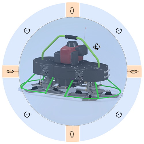
 to activate the view navigation interface. Colors and zones in the image are used to illustrate the zone boundaries and are not part of the UI. The Orbit default shortcut key is F4.

Pause the cursor over one a zone and observe the cursor change to indicate the click-drag behavior, then click-drag to do the orbit.
 Inside the circle orbit uses 3D spatial rotation. The pivot point is the circle center.
 Click-drag the mouse left-right to rotate the view about the vertical screen axis.
-
 Click-drag the mouse away or toward you to rotate the view about the horizontal screen axis.
 Click-drag the mouse around the circle to orbit normal to the screen.
- Left-click anywhere when any orbit cursor appears to define a new pivot center.
3-button mouse navigation features
 . When you access Free Orbit using this method, the behavior is as follows, with the:
- Full model in view: The pivot point is the model geometry center.
- Model partially in view: The pivot point snaps to the nearest edge/face/vertex of the nearest component.
- Model outside the view: The pivot point is the cursor location.
Constrained Orbit
- On the Navigation bar, click Constrained Orbit.
- Move the mouse left or right to rotate the view about the model space axis that passes through the TOP and BOTTOM faces of the ViewCube. This view is as if the model were on a turntable. It is equivalent to moving the eyepoint in an orbit about the object along lines of constant latitude.
- Move the mouse away or toward you to rotate the view about the horizontal screen axis, as if you were tilting the turntable. This view is equivalent to moving the eyepoint along lines of longitude.
Rotation is about the model space center point. The SteeringWheels CENTER command or other methods described elsewhere set the center point.
Rotate at Angle
Provides precise camera controls by accessing the 3D model environment while editing a drawing view.
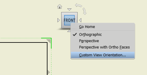
- In a drawing, double click a view to access the ViewCube for that view. Right-click the ViewCube, and click Custom View Orientation.

- A Custom View window opens. On the Custom view tab, click Rotate at Angle.

- Use the options in the Incremental View Rotate dialog to set the model orientation.