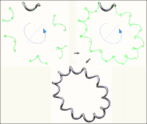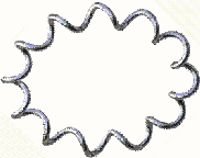
Follow these steps to create a coil with 12 revolutions. Begin by drawing construction lines based on the dimensions of the coil. The following are several of the basic commands that you use to create the 3D coil, including:
- Spline
- 2D and 3D sketch
- Revolve
- Extrude
- Sweep
- Circular pattern
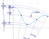
Step 1: Create a planar spline to represent one revolution of the spring
In a new part file, create a 2D sketch consisting of a single spline (and associated construction geometry) which represents one revolution of the spring. We recommend that one of the spline endpoints is coincident to a primary work plane and centered about a primary work axis.
Step 2: Create a circle to represent the diameter of the spring.
- On the ribbon, click 3D Model tab
 Sketch panel
  Create 2D Sketch .
 - Create a second 2D sketch consisting of a single circle which represents the diameter of the spring. The circle must be coincident with the end of the spline in the first sketch.

Step 3: Create construction geometry to define a path for the spring - Part 1
- On the ribbon, click 3D Model tab
 Create panel
  Revolve to revolve the surface.
 - Select surface output, and then select the circle as the profile and the Z axis.
- Enter 30 degrees as the angle. The angle is the length of one segment (revolution) of the coil.
- Flip the direction of the coil to the right.
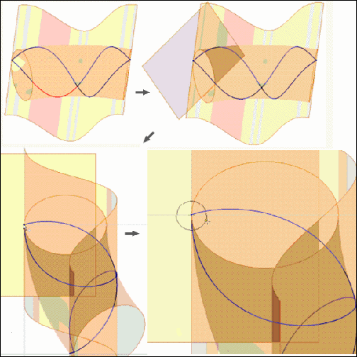
- Click OK to revolve the coil and generate a revolved surface tube enclosing the spline sketch.

Step 4: Create construction geometry to define a path for the spring - Part 2
- On the ribbon, click 3D Model tab
 Create panel
  Extrude .
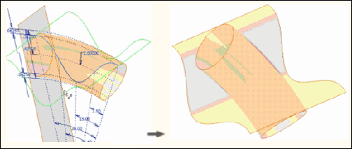
 - Extrude the spline sketch in both directions so that it intersects the coil in both directions. Specify Surface output to generate an extruded surface that intersects the revolved surface.
Step 5: Prepare for the Sweep command by creating a path for the spring
- On the ribbon, click 3D Model tab
 Sketch panel
  Create 3D Sketch .
 - Use 3D Intersection to create a 3d sketch on the intersection of the two surfaces, generating a path for the spring.
The line represents one revolution of the coil and creates a path for the coil to follow.

Step 6: Prepare for the Sweep command by creating a profile for the spring
- On the ribbon, click 3D Model tab
 Work Features panel
  Plane .
 - Create a work plane at the endpoint of one of the segments of the 3d sketch, normal to the selected segment. Note: Now there is a path and a work plane normal to the path. Next step is to sketch the actual cross section to sweep across the path.
- On the ribbon, click 3D Model tab
 Sketch panel
  Create 2D Sketch .
 - On the ribbon, click Sketch tab
 Create Panel
  Project Geometry .
 - Create a 2d sketch on the newly created work plane consisting of a single circle to represent the cross section of the spring wire. The center point of the circle must be coincident with the endpoint of the spring.
Step 7: Sweep one revolution of the spring
- On the ribbon, click 3D Model tab
 Create panel
  Sweep .
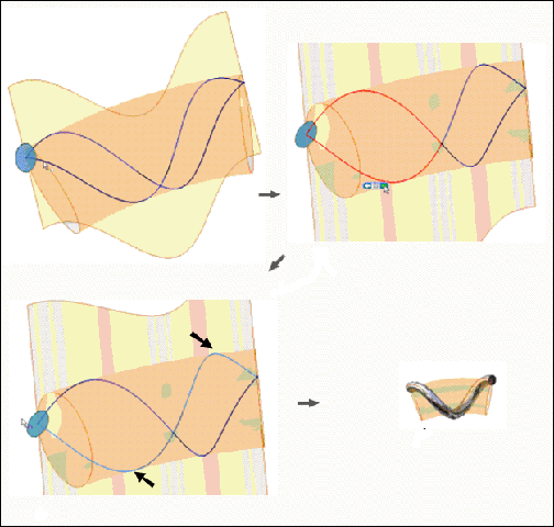
 The Sweep command automatically selects the profile of the model created in Step 6 since it is the only closed profile in the model.
- Select two contiguous segments of the 3d spline as the Sweep Path. Note:
 Select Other can be used to override undesirable segment chaining.
 One revolution is now selected.
- Click OK. One revolution of the coil spring displays around a curved axis.
Step 8: Pattern the Sweep feature to complete the spring
- On the ribbon, click Sketch tab
 Pattern panel
  Circular .
 - In the Circular Pattern dialog box, click Features, and then select Sweep in the browser.
- Click Axis, and then select the same axis used to create the surface revolve.
- Enter 12 for the Placement, and then enter 360 degrees for the angle.
- Click OK. The completed coil spring on a curved axes displays.
