Perform all measure workflows using the Measure tool panel.
What's New: 2020.2, 2020.3, 2022
Measure Overview
Measure can be used in the Assembly, Part, and Drawing environment.
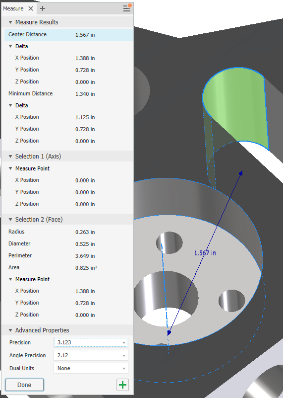
In the Measure tool panel you can:
- Specify the dual units and precision values. When one or more User Coordinate Systems (UCS) is defined in a file, you can specify the UCS to use. Results update if you change the value.
- In an assembly file, choose a selection priority from the tool palette: Component, Part, or Edges and Faces.
Note: The tool palette displays the selection priority options docked in a convenient location next to the property panel. The palette can be separated from the property panel and placed wherever you like. You can easily dock it with the property panel.
- Toggle between Minimum Distance, Center to Center, and Maximum Distance, for the distance delta value.
- Copy one or all values in the Measure tool panel.
In the graphics window:
- The geometry you select to measure remains highlighted in the graphics window.
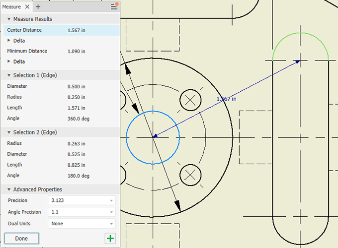
- The Measure selection set 1 and selection set 2 display different colors in the graphics window.
Note: You can change the color of the highlighted selections using Application Options
 Colors tab by selecting a color scheme from the Color Scheme list.
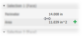
| Measure Linear Distance, Length, Angle, Loop, or Area | |
|
Information on each selection displays in the measure tool panel and in the graphics window. The Measure tool panel shows all possible values for your selections as well as the result from both selections. Clicking a value in the Measure tool panel displays the selection and the measurement in the graphics window. The value field column can be resized. Pause the cursor to the left of the value and click-drag to resize the column
To copy one or all values: Right-click a value and select Copy or Copy All from the context menu.
Note:
|
|
Use Measure to Enter Values in Dialogs
In most dialog boxes, you can use the Measure command to enter values .
- In a dialog box or property panel, on the drop-down list for a box that requires a value (for example, Taper or Distance in the Extrude dialog box), click Measure.
Note: Not all lists contain the option.
- In the graphics window, click to select the geometry to measure..
The measurement displays.