Several factors cause adjustments to the original length of wires, cables, ribbon cables, and segments in a harness assembly. These values are optional and are set as properties and harness settings.
Set service loop
- In the browser, double-click the harness assembly.
- In the browser, right-click the harness segment, and then select Harness Properties from the context menu.
- In the dialog box, click the Custom tab to add the Service Loop property.
- Click Apply to continue modifying or adding properties or OK to finish.
Set global slack
- Double-click the harness assembly containing the wires cable wire, and ribbon cable lengths, to adjust.
- Right-click and select Harness Settings.
- In the Harness Settings dialog box, click the Wires/Cables tab or the Ribbon Cables tab, and then set the global slack percentage value.
- Click Apply to continue making changes in the dialog box, or OK to close.
Set round-up
The wire and cable adjusted length values are dependent on the round-up values and the Apply round up to individual segments and exposed wire lengths setting. The ribbon cable adjust length value is dependent on the round-up values.
- Double-click the harness assembly containing the wire lengths, cable wire lengths, or ribbon cable lengths to adjust.
- Right-click and select Harness Settings.
- In the Harness Settings dialog box, click the General tab, and then click the arrow to select a round-up value from the list.
- If round-up is any value other than None, click the Calculate length as sum of rounded exposed wire pieces and segments if desired.
- Click Apply to continue making changes in the dialog box, or OK to close.
Examples showing the effect of Round-up and the Calculate length as sum of rounded wire pieces and segments in the nailboard
Example 1: Round-up value set and Apply round up to individual segments and exposed wire lengths check box enabled.
When the adjusted length round-up value is other than None and the Apply round up to individual and segments and exposed wire lengths setting check box is enabled, all wire and cable lengths in the nailboard add up to the wire or cable's adjusted length.
Adjusted Length of Wire= 16.0

Example 2: Round-up value set and Apply round up to individual segments and exposed wire lengths check box disabled
When a round-up value is set, but the Apply round up to individual segments and exposed wire lengths check box is disabled, the round up value of the wire's adjusted length value equals the sum of the values of the separate entities. The individual values are rounded, but the values of the separate entities may not. The wire's adjusted length calculation changes such that the round up on the wire length is done on the value of the addition of wire stubs and exposed wires and segments.
Adjusted Length of Wire= 14.5

Example 3: Round-up value None and Apply round up to individual segments and exposed wire lengths check box disabled
When round up is set to None, then the dimensioning of the segments and exposed wire pieces reflect the actual length except for the wire stubs. The wire stubs still have the embedded length and global slack, if any, distributed equally to each end.
Adjusted Length of Wire= 14.44

Set embedded length
Embedded length is used to adjust calculated wire lengths when it is used on parts, splices, and pins.
- Set Embedded Length as a custom property on a part, splice, or pin. Set the value at either the definition or occurrence level.Note: Both positive and negative embedded length values are allowed for splices.
- Double-click the harness assembly, right-click and select Harness Settings.
- In the Harness Settings dialog box, click the Wires/Cables tab.
- Click the check box to select the objects on which to look for the embedded length property.Note: If both parts and splices and pins are selected, the pin embedded length value overrides the part or splice value.
- Click Apply to continue making changes in the dialog box, or OK to finish.
Examples of Embedded Length
In the examples, both parts and pins are selected for the Embedded Length harness settings for wires and cables.
Example 1:
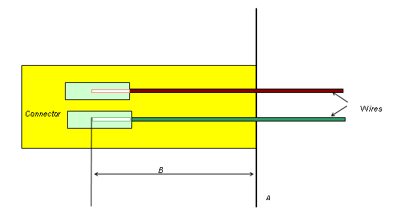
In this example, the connector has an Embedded Length property that is applied to all wire occurrences connected to it.

A: The plane on which all pins of the connector are modeled.
B: The distance between plane A and the point where the inserted wire ends. This is the embedded length value of the electrical component.
Adjusted length = Original wire length + B.
Example 2:
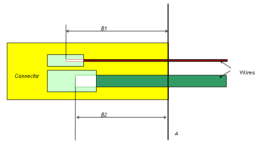
This example shows a complex connector that accepts both large and small wires. Since the large wire's pin cavity is embedded into the connector a different amount than the smaller wire cavity, an embedded length property is placed on the connector. The property value is equal to the most common embedded length for the majority of the pin cavities.

A: The plane on which all pins of the connector are modeled.
B: The distance between plane A, and the point where the inserted wire ends. For a connector with differing cavity sizes, B could be different for each wire inserted depending on the depth of the cavity. In this example, B could be equal to either B1 or B2.
B1: The distance between plane A and the point where the inserted wire ends for pin cavity B1.
B2: The distance between plane A and the point where the inserted wire ends for pin cavity B2.
Adjusted length of smaller wire = Original wire length + B1
Adjusted length of larger wire = Original wire length + B2