Sets the preferences for working with assemblies.
Access
File  OptionsAssembly tab
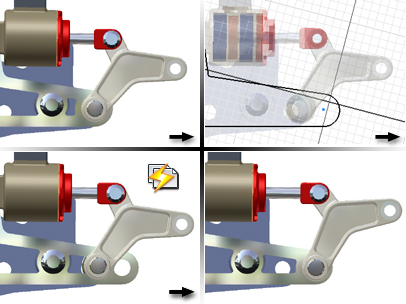
Defer update
Sets preference for updating assemblies when you edit components. Defer Update applies to Assembly constraints, Joints, iMates, and Adaptive components. There is a slight behavior difference between adding new constraints and adding new joints. When you add joints components move into place. However, when you add constraints components will not move into position until an update is done or the component is dragged. Updates to the graphics display occur regardless of this setting.
Select the box to defer updates of an assembly until you click Update for the assembly file. Clear the check box to update an assembly automatically after you edit a component.
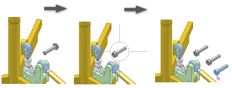
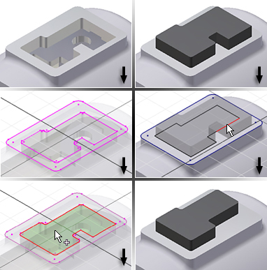
Delete component pattern sources
Sets default behavior when deleting pattern elements. Select the check box to delete the source component when deleting a pattern. Clear the check box to retain the source component instances when deleting a pattern.
Enable relationship redundancy analysis
Specifies if Inventor analyzes all assembly components for adaptivity adjustments. Default setting is not selected.
- Not selected
-
When the check box is cleared, Inventor skips a secondary analysis which normally checks for redundant relationships and analyzes all component degrees of freedom. The system only updates degree of freedom analysis when the symbols are displayed.
- Selected
-
When the check box is selected, Inventor performs a secondary analysis, and notifies you when redundant relationships exist. Degrees of freedom are updated, even when they are not displayed.
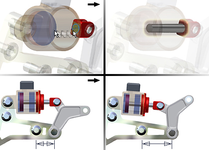
Features are initially adaptive
Controls whether newly created part features are made adaptive automatically. The check box defaults to not selected.
Section all parts
Controls whether parts are sectioned in an assembly. Children of parts have the same section view behavior as parents. The default is not selected (parts are not sectioned in assemblies).
Use last occurrence for component placement
Controls whether components placed in an assembly inherit the same orientation as the last occurrence of the component in the browser.
Relationship audio notification
Select the check box to play a tone when a relationship is created. Clear the check box to turn off sound.
Display component names after relationship names
Specifies if Inventor appends the component instance names to the relationships in the browser.
- Not selected
-
When the check box is cleared, Inventor does not display the component instance names with the relationship. For example, if constrain 12 is a Mate constraint between rod:1 and cylinder:1, the browser displays:
 Mate:12
- Selected
-
When the check box is selected, Inventor displays the component instance names with the relationship:
Mate:12(rod:1, cylinder:1)
Place and ground first component at origin
Specifies if the first component placed in an assembly is grounded at the origin.
- Not selected
-
When the check box is cleared, the first placed component is not grounded.
Tip: Right-click and use the context menu to ground any component at the origin. - Selected
-
When the check box is selected, the first placed component is grounded at the origin.
In-place features
When creating a part in place in an assembly, you can set options to control in-place features.
From/to extents (when possible)
Mate plane
Constructs the feature to the desired size and mates it to the plane, but does not allow it to adapt.
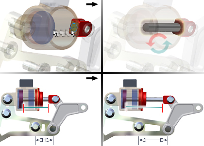
Adapt feature
Automatically adapts the in-place feature size or position when the plane on which it is constructed changes.
Cross part geometry projection
Enable associative edge/loop geometry projection during in-place modeling When creating a part or feature in an assembly, creates a reference sketch by projecting selected geometry from one part into the sketch of another part. The projected geometry is associative and updates when changes are made to the parent part. Projected geometry can be used to create a sketched feature.
The default setting is On. Clear the check mark to turn sketch associativity Off.
Enable associative sketch geometry projection during in-place modeling When creating or editing a part in an assembly, sketch geometry from another part can be projected into the active part. When this option is enabled, the projected geometry is associative and updates when changes are made to the original geometry. The part that contains the sketch is made adaptive automatically.
Component opacity
Determines which components display in opaque style when an assembly cross section is displayed. Click to select the desired display option.
- All
-
All components are shown with an opaque display style (when the display is shaded or shaded with edges displayed).
- Active only
-
Emphasizes active parts by displaying them as opaque while dimming inactive parts. This display style overrides some settings on the Display Options tab.
Appearance panel
Transparency Off or Transparency On command to set component opacity.
Zoom target for place component with iMate
Sets the default zoom behavior for the graphics window when placing components with iMates. Click to select the desired display zoom option.
- None
-
Leaves the view as it is. No zoom is performed.
- Placed component
-
Zooms in on the placed part so that it fills the graphics window.
- All
-
Zooms the assembly so that all elements in the model fit in the graphics window.
Express mode settings
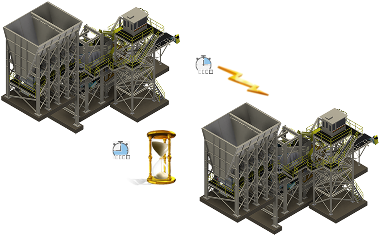
Specifies if the Express Mode command is enabled in the Assemble toolbar and express data is saved to the assembly file. Enable Express Mode to significantly improve file open times for large assemblies.
Enable Express mode workflows (saves graphics in assemblies) Select to save enhanced display and model data in the assembly (.iam) file. Clear the check box to disable saving Express Mode data in the assembly file. Some commands and functions are not available in Express Mode. You cannot clear the check box with documents open.
File Open Options
- Open Express when referenced unique files exceeds Sets the threshold used to determine the default mode for opening assembly files (Express vs. Full). Choose a number that represents meaningful file open performance improvement for assembly models. File open times are based on factors such as number of occurrences, complexity of model geometry, and system hardware specifications.
- Open Full Select to open the assembly file with all component data loaded. All commands and functions are available.
Import
- Import
- Imports Application Options settings from an .xml file. Click Import to display the Open dialog box. Navigate to the desired file, and then click Open.
- Use AutoCAD Related Settings
- Provides a feel similar to AutoCAD settings.
- Use Inventor Settings
- The default Application Options settings are installed.
Export
- Export
- Saves the current Application Options settings in an .xml file. Click Export to display the Save Copy As dialog box. Select a file location, enter a file name, and then click Save.
Default install locations for both Import and Export operations: Users\[login]\AppData\Local\Autodesk\Inventor [version]\Preferences.