Apply corner seams manually, or automatically while creating other features.
Options all corner seams define how the faces meet along the seam (distance and positions), and how the bends are relieved in the flat pattern. The default settings for the sheet metal rule define the default values for the options. You can change the values for an individual corner.
An automatic corner feature occurs when you create two flange features using identical parameters on adjacent edges of a sheet metal face.
A single flange or contour flange feature can contain multiple corners.
Corner seam gaps
- Face/Edge Apply a seam gap based on a measurement from the flange. Available only for corner seams are applied using Corner Seam. Corner seams created in releases of Inventor before R2008 use this method exclusively. The Flange and Contour Flange features do not use this method.
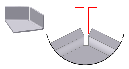
- Maximum Gap Distance Apply a seam gap that you can measure. You slide an inspection gage of a thickness equal to the supplied gap distance value between and along the edges and faces of the corner. Most useful for nonsquare corners (angles greater or less than 90 degrees). The Flange and Contour Flange features use only this method for automatic corners. The enlarged gap detail of the part in the following image illustrates the increased control in specifying gaps:
Create a Three-Bend Corner Seam
You can create a three-bend corner with Corner Seam or use Auto-Miter. Usually, when you use the Flange or Contour Flange dialog’s Corner tab, you use Auto-Miter to create three-bend corners.
You can also do this manually from two nonintersecting flanges. (One flange is typically an offset flange.)
When you create the flat pattern, the corner relief type and radius size specified in the Corner tab of the feature applies. It does not display in the folded model.