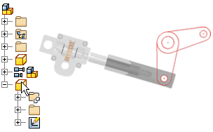
You create a layout in a 2D part sketch. The layout uses 2D sketch geometry to represent the design footprint and components. Sketch blocks are used to group geometry into rigid shapes that are repeated in the design. Also, you can define nested sketch blocks and place flexible instances of these blocks to explore kinematics of a design.
In a part file, you simply create a 2D sketch to begin your layout. If you are in an assembly file, you can start a layout with the Make Layout command. This command creates a part in the assembly and in-place edits the part so that you can create your layout sketch.
Add and constrain geometry to your sketch to represent your design layout. Once your layout has matured, use the Make Components and Make Part commands to derive selected sketch blocks into new part and assembly files.