To define a new release, select beam, and specify the released degrees of freedom at the start and the end of the beam element. Releases are defined in the beam coordinate system.
Note: When there are two or more adjoining beams, one of them should be fixed without a release at that beam end. Constraint already contains information about boundary conditions of adjoining beam.
The beam start and end tabs allow you to specific the beam release behavior independently on each end of the beam. The Beam coordinate system is shown while editing, closer to the start end of the beam.
Also, when you define a release, symbols of degrees of freedom display at start and end node of the beam in the graphics window. “x” represents “fixed” type, “f” represents “uplift none” type, “f+” represents “uplift +” type, and “f-” represents the “uplift-“ type. For example: Symbol “xxxffx” displayed in the graphics window means that the given start or end of the beam is connected with fixed displacement for X, Y, Z axes. Also, it is with uplift none (free) for rotation along X and Y axis also with fixed rotation along Z axis.
The Elastic and Partial stiffness coefficients adjust the method in which you can add stiffness to a given degree of freedom.
|
|
-
On the ribbon, click Frame Analysis tab  Connections panel Release Connections panel Release
-
Select a beam where you want to define a release. A beam coordinate system displays. It is positioned closer to start of the beam, the coordinate system is oriented towards the end of the beam. Also, symbols of degrees of freedom at start and end node of the beam display. Following symbols are used:
- “x” means “fixed” type of displacement or rotation
- “f” means “uplift none” type of displacement or rotation
- “f+” means “uplift+” type of displacement or rotation
- “f-” means “uplift-“ type of displacement or rotation
-
Select the coefficient that is used to define the values of displacement and rotation:
Select Elastic coefficient to define the exact values in N/mm. The elastic coefficient (such as, the elastic coefficient for the UZ direction) can be defined only for the released direction (that is, for the direction UZ).
Select Partial stiffness coefficient to enter values between 0.0 (a released direction) and 1.0 (no release). The value of the element stiffness is multiplied by the value of the coefficient at the appropriate end.
-
Specify the displacement. Use the drop-down menus to specify the degrees of freedom to release at the beginning and the end of the beam element for X, Y, and Z axis.
When you select Fixed type, there is no release in this direction.
“Uplift” options mean not fixed options. Uplift none, Uplift+ and Uplift- specify release displacements Ux, Uy, or Uz in the beginning or in the end node of the beam element, in the compatible ("+") or opposite ("-") direction with respect to the axis of the beam local coordinate system.
-
Specify the rotation. Use the drop-down menus to specify the degrees of freedom to release at the beginning and the end of the beam element for X, Y, and Z axis.
When you select Fixed type, there is no release in this direction.
Uplift none, Uplift+ and Uplift- specify release rotations Rx, Ry, or Rz in the beginning or the end node of the beam element, in the compatible ("+") or opposite ("-") direction with respect to the axis of the beam local coordinate system (according to the principle of the right-hand screw).
|
Note: Releases are defined in the beam coordinate system.
To remove a release, select the release in the browser, right-click, and select Delete.
Assigning a release to modify the behavior of individual beams
Release can be used to modify the behavior of individual beams.
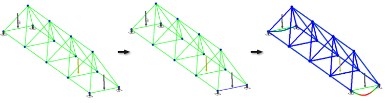
In the following example, there are two identical forces, they have the same size and direction.
Assign a release. On the ribbon, click Frame Analysis tab Connections panel Release  . We select a beam to release so that it can rotate.
Run the simulation. Click the  Simulate command in the Solve panel.
The loads are equal, but the displacement on the released beam is substantially bigger.