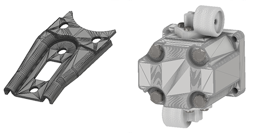
You can import and export mesh geometry, add work features, constrain mesh geometry, measure, create surfaces, and more.

Mesh geometry is a common exchange currency for 3D models. Mesh data, while it can be stored in a CAD native format, often is exchanged or shared in a neutral format such as STL or OBJ.
Use mesh data as reference geometry in assemblies to provide a spatial reference for designing components and thereby eliminating downstream revision costs.

Because mesh data is composed of triangles the exported resolution of the data affects the display and interpretation of the data by drawing annotations. Mesh geometry displays with varied fidelity depending on data resolution and the Inventor document in which it is used.
- Interoperability and collaboration
- Import OBJ or STL geometry into a Part or Assembly model
Note: Mesh models cannot be imported as reference models, only as converted models, and are not associated to the original file. If the original model changes, it would have to be imported anew.
- Export geometry (solid, surface, or mesh) in OBJ, STL, or DWF format
- Import OBJ or STL geometry into a Part or Assembly model
- Part and Assembly Modeling
- Create faces from selected mesh facets
- Add work features associated to mesh geometry
- Create 2D sketches on mesh planar faces
- Project mesh edges and vertices into 2D sketches
- Use Section View
- Use the measure distance or angle commands on mesh geometry
- Assign appearances to mesh objects
- Define and use view representations
- Use the Assemble, Joint, and Constrain commands on mesh geometry to infer relationships
- Presentations
- Mesh objects are treated the same as solid objects and can be tweaked like any other object
- Mesh objects points, and edges can be used for tweak direction
- Drawings
As mesh data is expected to be used for reference purposes, limited drawing support is provided. Mesh objects participate in drawings in the following ways:
- Objects display in precise and raster drawing views - base, projected, auxiliary, section, & detail
- Objects can be annotated, but not to the same extent as solid and BREP objects.
Note: Mesh edges do not have an individual visibility toggle. They are visible by default.
View Navigation
When navigating the view using orbit, pan, and zoom, we recommend that you set the model display to Shaded Visual Style. Mesh models are made up of many faces, edges, and vertices which can impact graphic performance for certain display tasks.
An Example of Using Mesh and Fit Mesh Face for Drawing Use
Scenario: I have an assembly with low resolution mesh reference geometry. In the assembly drawing I need to dimension between a mesh reference geometry hole center and a feature in a solid component I designed.
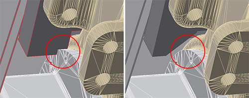
Low resolution mesh cannot be annotated with a hole centerline because tessellation is too coarse. How do I resolve this for drawing purposes?

- In the mesh model, use Fit Mesh Face to create surfaces for one mounting hole in the pattern that I need to reference with dimensions.
- Using Fit Mesh Face, create the cast hole whose axis will be used for the pattern.
- Launch the radial pattern command and select the mounting hole face created in step 1.
- Click Rotation Axis and select the cast hole surface.
- Click OK.
- I can use the drawing tools to dimension between the mesh with BREP objects and the solid model of the part.