Defines the values for a bend shape, transition, and parameters, and overrides the default values.
The active Sheet Metal rule determines the bend options for the current sheet metal part. This rule is set for the part in the Sheet Metal Defaults command. On this tab of the dialog box, you can override the values for the bend shape, transition, and parameters for the feature that you are creating.
- Access
- In the feature creation dialog box, click the Bend tab while creating a sheet metal bend, contour flange, face, flange, fold, or hem.
- Relief Shape
- Accepts the Default relief shape specified in the Sheet Metal Style, or defines the shape as one of three supported reliefs.
- Straight

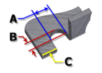
- A bend relief shape defined by square corners that is common in manual shop situations and often produced by a saw kerf. In the following illustration, each parameter defaults to the value defined in the Sheet Metal style. With this option, you can edit them individually for a feature.
- A Bend relief width.
- B Bend relief depth beyond the deformation zone.
- C Size of the material remnant following creation of the bend with relief.

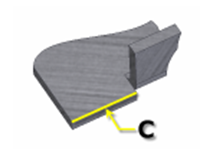
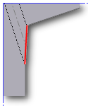
- Tear

- An acceptable bend relief resulting from material failure. Common when tight bends are required, and with certain materials. In the following illustration, C represents the size of the material remnant following creation of the bend with relief. This parameter defaults to the value defined in the Sheet Metal Style. With this option, you can edit it individually for a feature.
- Round

- A bend relief shape defined by a cut ending with a semicircle. It is often produced using laser cutting technology. In the following illustration, each parameter defaults to the value defined in the Sheet Metal style. With this option, you can edit them individually for a feature.
- A Indicates the bend relief width (diameter)>
- B Indicates the bend relief depth beyond the deformation zone to the tangent point of the diameter.
- C Represents the size of the material remnant following the creation of the bend with relief.
- Straight
- Relief Width
- Defines the width of the bend relief. Defaults to the parameter BendReliefWidth as defined in Sheet Metal Styles. Identified as A in the dialog box illustration.
- Relief Depth
- Defines the depth of the bend relief. Defaults to the parameter BendReliefDepth as defined in Sheet Metal Styles. Identified as B in the dialog box illustration.
- Minimum Remnant
- Defines an acceptable size for the minimum stock allowed to remain along side of a bend relief cut. (Any remainder smaller is eliminated from the model.) Defaults to the parameter MinimumRemnant, as defined in Sheet Metal Styles.
- Bend Transition

- Defines the condition that shows in the flat pattern of the bend. The folded model shows either the transition type of None (for all transition types except Trim), or the type Trim if that is the selected type. The following images show the transition types for this folded model.
- None

- Depending on the geometry, results in a spline between the edges of the two faces meeting at the selected bend.
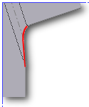
- Intersection

- Results in a straight line from the edge of the bend zone which intersects the edge of the bent feature.
- Straight Line

- Results in a straight line from one edge of the bend zone to the other.
- Arc

- Requires entry of an arc radius value, and results in an arc of that size tangent to the edge of the bent feature and what is a straight transition.

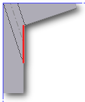
- Trim to Bend

- Displays in the folded model, and results in a cut to the bend zone perpendicular to the bent feature.
- None