All loads use Heads Up Display (HUD) and grips to define the inputs easily. More complex settings are available in the dialog boxes. When you select Use HUD in Application option in the Frame Analysis Settings dialog box , Heads Up Display is used as default input and edit method.
Loads are part of the boundary conditions you define for the simulation. There are various load types that can be applied. The available load types are:
| Access | Load Type | Inputs | Used to... |
|---|---|---|---|
|
|
Force | Beam or node |
Apply a force of the specified magnitude to the selected beam or node. |
|
|
Continuous Load | Beam | Apply a load of the specified magnitude around the axis and perpendicular to the beam or node. |
|
|
Moment | Beam or node | Apply a load of the specified magnitude around the axis and perpendicular to the beam or node. |
|
|
Axial Moment | Beam | Apply a load of the specified magnitude in the plane perpendicular to the beam axis. |
|
|
Bending Moment | Beam | Apply a load of the specified magnitude in the plane parallel to the beam axis. |
To apply a load:
- In the Loads panel, click the load type that you want to apply. The applicable load dialog box displays. Or, you can select the position of load directly.
Note: You can also right-click the Loads node
 in the browser and select the appropriate load type from the context menu.
- The selector command is active so that you can immediately begin selecting inputs in the graphic region. Based on the load type, make the corresponding selection.
- The selection displays a glyph indicating the direction in which the load is applied. If the load direction is not what you need, use the vector components in the expanded section (for applicable load types) to describe the direction.
- To display a corresponding dialog box, right-click in the graphics window, and select More Options.
To apply a force
Apply a force of the specified magnitude to the selected beam or node.
|
|
|

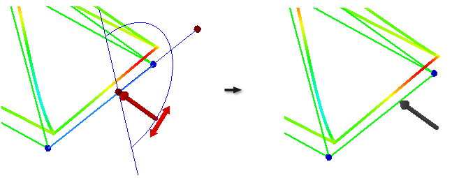
To apply a moment
Moment is applied around the beam axis in the specified plane. By default, the plane where moment is applied is perpendicular to the beam axis.
|
|
|
To apply an axial moment
Use this procedure to apply axial moment on beams. Axial moment is applied in the plane perpendicular to the beam axis.
|
|
|
To apply a bending moment
Use this procedure to apply bending moment on beams. Bending moment is applied in the plane parallel to the beam axis.
|
|
|