Parts in assemblies that fit together must frequently change size to accommodate design changes. Create a part in-context of an assembly and project edges, loops, faces, or sketch geometry from one part into the sketch of the part. The cross-part sketch geometry can be used to constrain other sketch geometry or to create a feature. Cross-part sketch geometry is adaptive and automatically updates when the parent part changes.
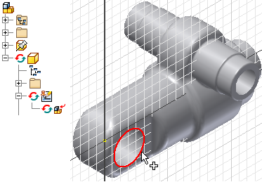
For example, an assembly has a part with a sleeve that fits over a shaft on another part. You can project the shaft end into the sketch to represent the inner diameter of the sleeve. You extrude the profile to create the sleeve extrusion. The sleeve is adaptive to the shaft and automatically updates to changes in the shaft diameter.
The size and position of the cross-part sketch is based on the parent part. A cross-part sketch can be used like any other sketch geometry to create a feature in the new part.
- Edge

- Face (outer and inner boundaries of face are projected)

- Loop

- Sketch geometry

- DWG geometry

The geometry, sketch, and part are adaptive
![]() .
.
Use the Cross part geometry projection options to control whether projected geometry is associative. Select the
File  OptionsAssembly tab. Under In-Place Features, select the checkboxes for Cross part projection to enable associativity when the geometry is projected.
- In an assembly, change the browser view to Modeling View.
- Expand the dependency and select Break Link.
- In the assembly, activate the part.
- Expand the part in the browser.
- Right-click the sketch and select Break Link.
Optionally,
The parts are now independent of one another.
You can control the adaptivity of the projected geometry, the sketch, or the part. Use the context menu to control adaptivity.