What's New: 2023
Defines constraint pairs called iMates to specify how parts connect when inserted in an assembly.
Symbols identify iMates. The symbols show the type and state of the iMate. You can rename a symbol to correspond with a matching constraint in other parts.
Multiple iMates can be defined on a single part.
- Access
-
Ribbon:
Manage tab
 Author panel
iMate
Author panel
iMate

- Assembly tab
- Specifies one or more constraint types, geometry, and constraint names to define iMates. The first specified constraint is the primary iMate.
- Type
- Specifies the constraint type to match when the part is inserted and constrained in an assembly.
- Mate constraint

- specifies that the selected face is positioned face to face or adjacent and flush to another face on a component with a matching iMate.
- Angle constraint

- Specifies the allowed angle of the selected edge or planar face when positioned relative to another component with a matching iMate.
- Tangent
constraint

- Requires contact of the selected face, plane, cylinder, sphere, or cone at a tangent point on a component with a matching iMate.
- Insert constraint

- Requires a face-to-face mate constraint between planar faces and a mate constraint between axes on a component with a matching iMate.
- Mate constraint
- Selection
- Selects the geometry on the part to constrain to an iMate on another part.
- Offset or Angle
- Specifies distance or angle by which the iMate halves are offset from one another.
- Solution
- Shows the relationship defined when the part is constrained to a matching iMate in an assembly.
- Motion tab
-
- Type
-
- Rotation motion constraint

- Specifies rotation of one component relative to another using a specified ratio. Cylindrical faces default to the geometric ratio between the selected cylinders.
- Rotation-Translation motion constraint

- Specifies how two components translate relative to each other using a defined ratio.
- Rotation motion constraint
- Selections
- Selects geometry on two components to constrain together. You can specify one or more curves, planes, or points to define how pieces fit together.
- Ratio or Distance
-
- Ratio
- For Rotation constraints, the ratio specifies how much the second selection rotates when the first selection rotates. For example, a value of 4.0 (4:1) rotates the second selection four units for every unit the first selection rotates. A value of 0.25 (1:4) rotates the second selection one unit for every four units the first selection rotates. The default value is 1.0 (1:1). If two cylindrical surfaces are selected, a default ratio computes and displays that is relative to the radii of the two selections.
- Distance
- For Rotation-Translation constraints, the distance specifies how much the second selection moves relative to one rotation of the first selection. For example, a value of 4.0 mm moves the second selection 4.0 mm for every complete rotation of the first selection. If the first selection is a cylindrical surface, a default distancecomputes and displays that is the circumference of the first selection.
- Solution
- Specifies whether the motion is forward or reverse. Click the appropriate button.
Name and Matching List
You can select a component using the Place Component dialog box, and select either Interactively place with iMates or Automatically generate iMates on place. If at least one component is already placed in the assembly, iMates are matched. You can increase the accuracy of the results by creating a Matching List.
- Name
- Creates an iMate name. You can enter a name or leave blank and a default name is automatically created.
- Matching List
- Creates a list of iMate names. When a component is placed, matching first attempts to find a name in the list, and then to match iMate properties.
- Add Name to List

- Adds a name. Click it and then enter a name.
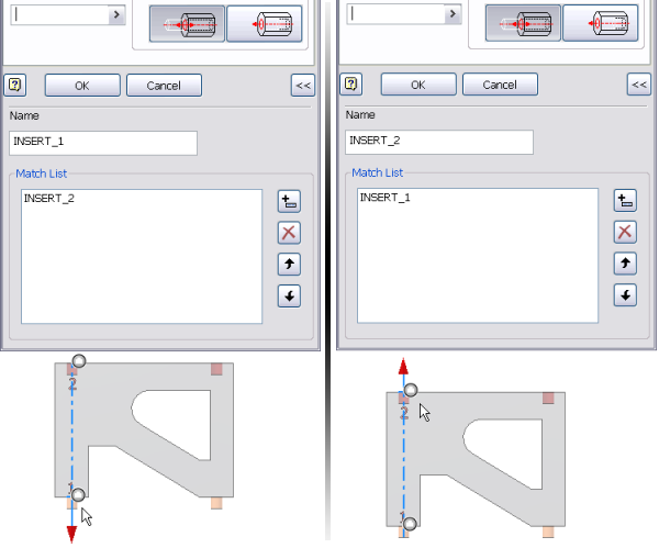
In this example, multiple instances of a component are assembled in ladder form. To accomplish it, an iMate matching list is created so Post 1 is always placed into Hole 2.
- Create an iMate insert constraint named Insert_1 on Post 1. Expand the dialog box and create the preferred match (Insert_2) as the first entry in the matching list.
- Create an iMate insert constraint named Insert_2 on Hole 2. Expand the dialog box and create the preferred match (Insert_1) as the first entry in the matching list.
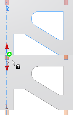
- Place the first instance of the component into an assembly.
- Place the second instance of the component using the Place Component dialog box. Enable either iMate option (Interactively place with iMates, or Automatically generate iMates on place).