Sets the selection mode filters in the QAT.
Parts
- Select Bodies

-
Selects solid or surface bodies on the part.
- Select Features

-
Selects features on the part. You can highlight and select features, or the individual curves that define features.
- Select Faces and Edges

-
Sets the command to select faces and edges on the part.
- Select Sketch Features

-
Selects sketch geometry used to create features. You can also highlight and select sketches, or the individual curves that define sketches.
- Select Annotations

-
Selects 3D Annotations on the part. You can use this filter to select multiple 3D annotations to control visibility in each view.
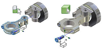
Selection set of Faces or Edges Tangent to the Preselected Face(s) or Edge(s)
Create a selection set of all the faces or edges tangent to each other in a Part, Assembly, or Sketch. In the graphics window:
- With the left mouse button, double-click a face or an edge.
- In the part or assembly environment:
- Select one or more faces or one or more edges, right-click and select
Select Tangencies from the context menu.
Note: Hold down the CTRL key to select more than one face or edge.
- Select one or more faces or one or more edges, right-click and select
Select Tangencies from the context menu.
- In the sketch environment:
- Select a face or an edge, right-click and select Select Tangencies from the context menu.
OR
Drawing Select Modes
Sets the selection mode and filter set, and selects the elements to work with in drawings.
Access
On the Quick Access toolbar, click the arrow on the Select command.
Select modes
Sets the mode for selecting elements of parts and assemblies in drawing views.
- Select Edge Priority
-
Selects edges on parts.
- Select Feature Priority
-
Selects features on parts.
- Select Part Priority
-
Selects parts.
- Select All Inventor Dimensions

-
Selects all dimensions in the current sheet, and places them in a new selection set.
- Select All Model Dimensions

-
Selects all model dimensions in the current sheet, and places them in a new selection set.
- Select All Overridden Dimensions

-
Selects all overridden dimensions in the current sheet, and places them in a new selection set.
Note: Overridden dimensions are dimensions with values that you either changed, or hid their values. - Select All AutoCAD Dimensions

-
(available for DWG files only) Selects all AutoCAD dimensions in the current sheet, and places them in a new selection set.
Select Filters
Specifies a filter set that determines which elements you can select when working in a drawing. You can customize the filter sets using Select Filters. Click a filter set to apply it.
- Edit Select Filters

-
Opens the Select Filters dialog box, where you can specify filters to activate for each filter type. You can select or clear filters on the list of all filters.
- Select All

-
Applies all selected filters in all filter types to elements in a drawing.
- Layout filter type

-
Activates the specified filter types to apply to drawing views.
- Detail filter type

-
Applies a filter set to select details such as dimensions, centerlines, center marks, and text. Suppresses selection of other elements, such as symbols.
- Custom filter type

-
Applies a customized filter set.
Drawing Filters
Specifies the elements that you can select when using the Select command filter sets in drawings.
Access
On the Quick Access toolbar, click the arrow on the Select command and then click Edit Select Filters.
- Filter set
-
Specifies the Custom, Detail, or Layout, filter set to change. Click the arrow, and select the filter set from the list.
- Filters
-
Lists the filters available for the selected filter type. You can select the selected filters in the drawing. Click to add a filter, or clear the check mark to omit the filter from the set.
- Select All
- Selects the entire list, and makes them available in the drawing.
- Select None
- Clears the check mark from all filter types.
- Invert Selection
- Switches between selected and unselected filters.
Assemblies
Sets the selection mode, and selects the elements to work with in assemblies.
Access
On the Quick Access toolbar, click the arrow on the Select command.
- Component Priority

-
Sets the command to select complete components. A component can be a part or subassembly. You cannot select a child part or component of a subassembly.
- Part Priority
-
Sets the command to select parts whether they were added to the assembly as a single part or as a component in a subassembly. You cannot select features or sketch geometry for a part.
- Feature Priority
-
Sets the command to select features (including work features) on any part in the assembly.
- Select Faces and Edges
-
Sets the command to select faces on any part in the assembly. You can also highlight and select faces or the individual curves that define faces.
- Select Sketch Features
-
Sets the command to select sketch geometry used to create features. You can also highlight and select sketches or the individual curves that define sketches.
- Select Visible Only

-
Includes only visible components in a selection set. Select Visible Only is applied for all selection methods.
- Enable Prehighlight

-
Shows prehighlighting when the cursor moves over an object. The command is activated by default. In the assembly and weldment environments, when turned off, prehighlighting does not show during component or part selection priority.
This setting does not affect the Select Other command, which always shows prehighlighting.
The Enable Prehighlight command also is available from the Application Options dialog box, General tab.
Component selection options create a set according to specific criteria. You can use the selected set in other operations, such as adjusting visibility.
- Select All Occurrences

-
Selects all occurrences of the selected model in the current file.
- Constrained To

-
Selects and highlights components constrained to one or more preselected components.
- Component Size

-
Selects and highlights components of the size set in Select by Size. The diagonal of the bounding box of the selected components determines the size. You can click the arrow to select a component to measure its size. Select option to select components greater than or less than component size. You can use percentage, with 100% as the largest component size.
- Component Offset

-
Selects and highlights components contained within the bounding box of the selected components, plus an offset distance. Set the offset distance in Select by Offset, or click a face and drag to resize. Click the arrow to use the Measure command, if appropriate. Select the check box to highlight partially contained components.
- Sphere Offset

-
Selects and highlights components contained within a sphere surrounding the selected components. Set the sphere size in Select by Sphere, or click the sphere edge and drag to resize. Click the arrow to use the Measure command, if appropriate. Select the check box to highlight partially contained components.
- Select by Plane

-
Selects and highlights components on the specified side of a plane. Select the bounding plane and the side (direction) in Select by Plane. Select the check box to highlight partially contained components.
- External Components

-
Selects and highlights external components. Set Percentage Visible to adjust the sensitivity.
- Internal Components

-
Selects and highlights hidden (internal) components. Set Percentage Visible to adjust sensitivity.
- All in Camera

-
Selects and highlights all components "visible" in the current view plane. Set Percentage Visible to adjust sensitivity.
- Invert Selection

- Previous Selection
-
Reselects the previous selection set. Remembers only one previous set.
Presentations
Command Settings
- Component Priority
-
Selects complete components. A component can be a part or subassembly. You cannot select a child part or component of a subassembly.
- Leaf Part Priority
-
Selects parts whether they were added to the assembly as a single part, or a component in a subassembly. You cannot select features or sketch geometry for a part.