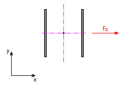
1. Loading by axial force F x
Resultant Shear Stress
![]()
where:
|
F x |
axial force [N, lb]. |
|
|
A |
throat area of the weld group [mm 2 , in 2 ]. |
2. Loading by bending moment M

Shear stress in the weld investigated point
![]()
where:
|
u |
constant |
|
|
- for calculation in metric units u = 1000 |
||
|
- for calculation in English units u = 12 |
||
|
M |
bending moment [Nm, lb ft] |
|
|
r |
radius vector of investigated weld point related to the weld group center of gravity [mm, in] |
|
|
J |
polar moment of inertia of weld group [mm 4 , in 4 ] |
3. Loading by bending force F Y
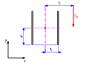
In any weld point, a stress caused by shearing force F Y and bending moment M F originates. Its size determines the formula:
M F = F Y r F [Nmm, lb in]
where:
|
F Y |
bending shearing force [N, lb] |
|
|
r F |
arm of bending force to the weld group center of gravity [mm, in]. |
Shear stress caused by shearing force
![]()
where:
|
F Y |
bending shearing force [N, lb] |
|
|
A |
throat area of the weld group [mm 2 , in 2 ]. |
Shear stress caused by bending moment
- stress x-component
![]()
- stress y-component
![]()
where:
|
M F |
bending moment [Nmm, lb in] |
|
|
r Y |
distance of investigated weld point to the weld group center of gravity in the y-axis direction [mm, in] |
|
|
r X |
distance of investigated weld point to the weld group center of gravity in the x-axis direction [mm, in] |
|
|
J |
polar moment of inertia of weld group [mm 4 , in 4 ] |
Resultant shear stress in the investigated point of weld
![]()
where:
|
τ XM |
x-component of shear stress caused by bending moment [MPa, psi] |
|
|
τ Y |
shear stress caused by shearing force F Y ' [MPa, psi] |
|
|
τ YM |
y-component of shear stress caused by bending moment [MPa, psi] |
4. Loading by common force F
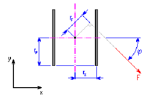
In any weld point, a common force F causes adequate stress to the stress which would arise by combined loading from bending moment M F and the pair of shearing forces F X ', F Y ' with action point in the weld group center of gravity, while applies:
M F = F r F [Nmm, lb in]
F X' = F cos ϕ [N, lb]
F Y' = F sin ϕ [N, lb]
where:
|
F |
acting force [N, lb] |
|
|
r F |
arm of bending force to the weld group center of gravity [mm, in] |
|
| ϕ |
direction angle of acting force [°] |
Shear stress caused by shearing force F X'
![]()
Shear stress caused by shearing force F Y'
![]()
where:
|
A |
throat area of the weld [mm 2 , in 2 ] |
Shear stress caused by bending moment
- stress x-component
![]()
- stress y-component
![]()
where:
|
M F |
bending moment [Nmm, lb in] |
|
|
r Y |
distance of investigated weld point to the weld group center of gravity in the y-axis direction [mm, in] |
|
|
r X |
distance of investigated weld point to the weld group center of gravity in the x-axis direction [mm, in] |
|
|
J |
polar moment of inertia of weld group [mm 4 , in 4 ] |
Resultant shear stress in the investigated point of weld
![]()
where:
|
τ X |
shear stress caused by shearing force F X' [MPa, psi] |
|
|
τ XM |
x-component of shear stress caused by bending moment [MPa, psi] |
|
|
τ Y |
shear stress caused by shearing force F Y ' [MPa, psi] |
|
|
τ YM |
y-component of shear stress caused by bending moment [MPa, psi] |
5. Calculation of comparative stress σ S
Comparative stress is determined from calculated partial stresses according to the formula:
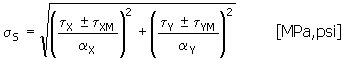
while for the x-component of stress that actuates in the investigated point of weld, perpendicularly to the weld direction, the α X = α 3 formula is applied. In the opposite case α X = α 4 . The same applies for the y-component of the stress actuating perpendicularly to the weld direction, that is α Y = α 3 or α Y = α 4 .
where:
|
τ X |
shear stress caused by shearing force F X' [MPa, psi] |
|
|
τ XM |
x-component of shear stress caused by bending moment [MPa, psi] |
|
|
τ Y |
shear stress caused by shearing force F Y ' [MPa, psi] |
|
|
τ YM |
y-component of shear stress caused by bending moment [MPa, psi] |
|
|
α 3 |
conversion factor of weld joint for fillet end weld [-] |
|
|
α 3 |
conversion factor of weld joint for fillet end weld [-] |