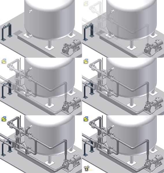
To activate the tube and pipe environment and begin adding rigid piping, bent tubing, and flexible hosing routes to an assembly, you must add a run to a standard Autodesk Inventor assembly. For the first pipe run added, the system creates the primary runs assembly along with an individual run.
Once the primary runs assembly is created, the tube and pipe run environment is activated so you can add routes and runs. As with the primary runs assembly, each run together with contained routes can be stored in a specific location in your work space by default. All routes and runs are arranged in the order they are added to the assembly.
Some routes start and end on assembly model geometry. Other routes branch or fork off a primary route to create a network of interconnecting rigid pipes, bent tubes, and flexible hoses which typically represent a single flow system. The routes can use the same style or several unique styles. With unique styles, it is possible to have flexible hose, pipe, and tubing with different diameters all as part of the same run.
Primary runs assembly, runs, routes, and hose assemblies can be reused using the Make Adaptive command. If you want to reuse a primary runs assembly, ensure that the top assembly does not contain any other adaptive primary runs assembly.
How are tube and pipe assemblies different from standard Autodesk Inventor assemblies?
Creating a primary runs assembly makes available the specialized Tube and Pipe, Pipe Run, and Route tabs and the Model browser. Use these tools to determine the forward route creation as dynamic or manual, and then insert fittings.
A series of 3D sketch commands such as Bend, Include Geometry, are used to introduce reference geometry so that geometric and dimension constraints can be placed to assist in route creation and edits. The 3D Orthogonal Route tool enables you to create intermediate route points at specific angular positions and distances, and reorient the route direction against reference geometry. You can also use points and rotations snapped from other geometry. Industry-standard fittings from the Content Center can be added and removed.
Tube and pipe styles are different from style standards in normal Inventor assemblies. They optimize the process for defining tube and pipe features. The style attributes contain criteria for route type, nominal diameter, minimum and maximum segment length, material, bend radius, and other details that are typically consistent throughout a route. The software applies these attributes as you design.
Can tube and pipe design be configured in an iAssembly factory?
When a tube and pipe iAssembly factory is created, the existing or newly created primary runs assembly is automatically included with an adaptive status as normal child components. When a new configuration row is added, a non-adaptive primary runs assembly for the new configuration row is added. Use the Make Adaptive command to transition it to the tube and pipe interchangeability set or modify the primary runs assembly members.
When a new configuration row is added in a tube and pipe iAssembly factory, the Non-Adaptive primary runs assemblies that are created automatically do not update when the configuration changes. Tube and pipe interchangeability set is introduced by applying the Make Adaptive command so that any given configuration can have unique routes and runs.