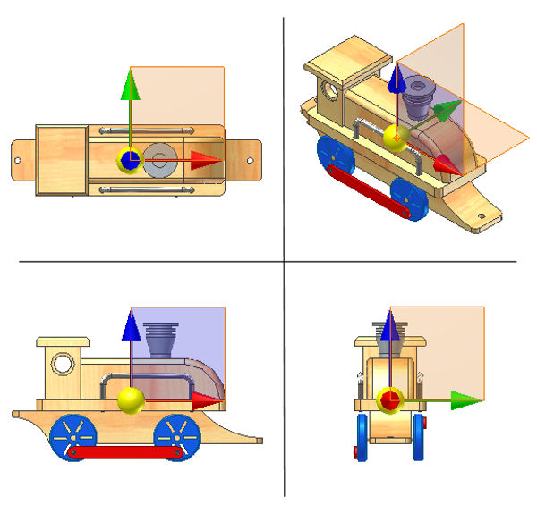
Shows the location of the center of gravity for a selected component.

The Center of Gravity (COG) triad contains a selectable sphere, three selectable work planes, and a selectable work point at the symbol origin. The COG work geometry is used for measuring distances and angles and "Look At" view select. The sphere and the work point at the center of the sphere show the location of the center of gravity for a selected component. The symbol also serves as a visual reference during the design process, such as when trying to keep the center of gravity within a particular region.
What happens to the COG when the mass properties are out of date?
When the COG is first displayed and the mass properties of a component are out of date, you are prompted to update. If you choose not to update, the COG is displayed in the last known location and the symbol is shaded. If the mass properties were never calculated, the COG is placed at the center of the bounding box. If several properties of the component become out of date while the COG symbol is displayed, it is shaded.
Use the Tools tab to update the mass properties and refresh the COG location and symbol display.
Can the coordinate location of the COG be displayed?
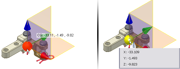
There are three methods to display the exact coordinate location of the center of gravity.
- Set the Select mode filter to either Feature Priority or Select Faces and Edges, pause the cursor over the sphere in the COG symbol and use the Select Other command until the sphere is highlighted. The coordinates display when you pause over the highlighted sphere.
- Initiate the Measure Distance command, pause the cursor over the work point and use the Select Other command until the work point is highlighted. After selecting the work point the coordinates are displayed in the Measure dialog box.
- Navigate to the iProperties > Physical tab and update the mass properties from the context menu.

Can the COG be selected?
Select the center of gravity work geometry for measuring distance and angle.