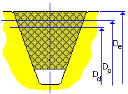
Belt length is determined in a datum or effective system. For this reason the datum or effective diameters are determined first for each pulley. The belt trajectory is based on individual pulley position. The sliding pulley position is adjusted to accomplish standard belt length criteria. The calculation uses iteration solution to find appropriate sliding pulley position what is closest to desired (or current) sliding pulley position.
Pulley diameters
|
|
Grooved pulley |
|
D e = D w + 2 h w |
|
|
D p = D w + 2 a |
|
|
D d = D w |
|
|
|
Flat pulley clockwise direction |
|
D e = D + 2 h |
|
|
D p = D + 2 (h - h w + a) |
|
|
D d = D + 2(h - h w ) |
|
|
|
Flat pulley counterclockwise direction |
|
D e = D |
|
|
D p = D + 2 (h w - a) |
|
|
D d = D + 2 h w |
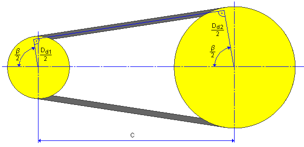
Example of power transmission with 2 pulleys
This example uses a datum system.

Arc of contact
![]()
Datum belt length
![]()
Center distance
![]()
Following formula is recommended when determining the center distance of a new drive
0.7 (D d1 + D d2 ) ≤ C ≤ 2(D d1 + D d2 )
Meaning of used variables:
|
D W |
Nominal diameter (datum or effective) [m] |
|
D e |
Effective (outside) pulley diameter [m] |
|
h w |
Nominal height (for effective system h w = 0) [m] |
|
a |
Pitch line offset (for effective system is negative) [m] |
|
D |
Flat pulley nominal and outside diameter [m] |
|
h |
Belt height [m] |
|
D d |
Pulley datum diameter [m] |
|
C |
Center distance [m] |
| β |
Arc of contact [deg] |
|
L d |
Datum belt length [m] |


