Use custom equations to specify exactly how you want to account for the flattening of the bend zones within your folded sheet metal part models.
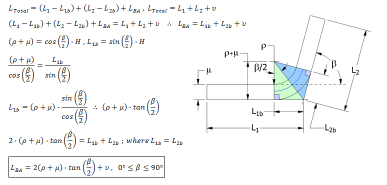
- A linear approximation using a defined KFactor
- Measured values captured in a bend table for specific materials, bend angle values and tooling
- Custom equations that provide uniform deformation within specified angular bounding conditions
Custom equations are defined within a named unfold rule that is defined using the Style and Standard Editor dialog box.
Bend Compensation Type
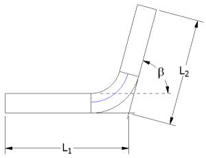
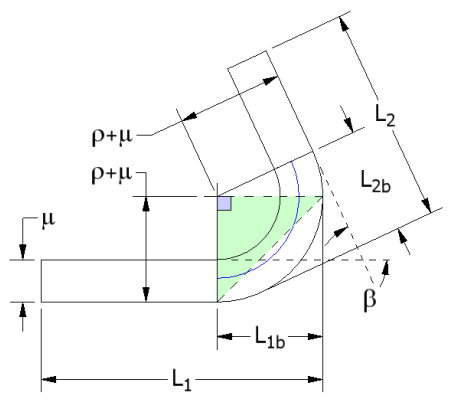
You use the bend compensation equation to determine the total developed length:
 . Is the total developed length.
  . Is the length from the first detail face to the virtual sharp.
  . Is the length from the second detail face to the virtual sharp.
  . Is the result of the bend allowance calculation. Inventor calculates a bending allowance using the following equations. For angular cases, where
  , Inventor uses the equation
  , where:
  . Is the bend angle.
  . Is the bend allowance length.
  . Is the bend plate inner radius.
  . Is the sheet thickness.
  . Is the result of the bend allowance calculation.
Expanding the original equation to include the bend allowance calculation results in:
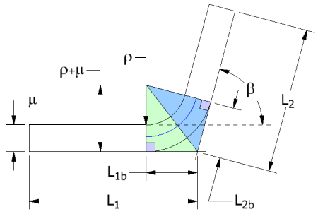
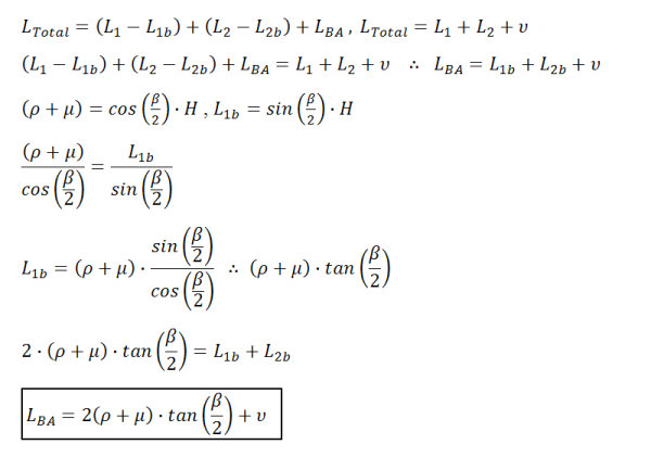
For angular cases where  , the following equation is used:
Expanding the original equation to include the bend allowance calculation results in:

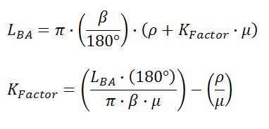
Once the bend allowance is determined, the KFactor can be derived using:
Bend Deduction Type

Use the bend deduction equation to determine the total developed length:
 . Is the total developed length.
  . Is the length from the first detail face to the virtual sharp.
  . Is the length from the second detail face to the virtual sharp.
  . Is the result of the bend allowance calculation.
The bend deduction equation provides a calculation method that is the direct opposite of the bend compensation method.
For bend deductions, Inventor calculates a bending allowance using the following equations.
For angular cases:
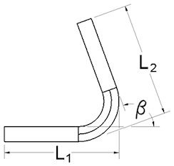
 , where:
  . Is the bend angle.
  . Is the bend allowance length.
  . Is the bend plate inner radius.
  . Is the sheet thickness.
  . Is the result of the bend allowance calculation.
For angular cases, where ![]() , the equation used is:
, the equation used is: ![]()
Bend Allowance Type
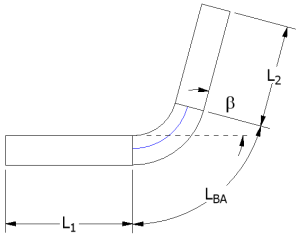
 . Is the total developed length.
  . Is the length of the first bend plate.
  . Is the length of the second bend plate.
  . Is the result of the bend allowance calculation.
A defined equation is supplied to solve for the bend allowance directly. The KFactor can be derived from the following equation:
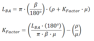
KFactor Type
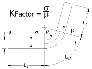
Determining the total developed length using the KFactor method uses the equation:
 . Is the total developed length.
  . Is the length of the first bend plate.
  . Is the length of the second bend plate.
  . Is the result of the bend allowance calculation.
The bend allowance is calculated using the following equation:
Edit Custom Unfold Equations
You can define four types of custom equations while editing a named unfold rule.
The equation type selected on the Style and Standard Editor determines the variable defining the left side of the equation. Character insertion keys on the Equation Edit dialog box provide single-click insert ability for: angle, radius, thickness, and Pi.
The variable type is defined by the Equation Type selected on the Style and Standard Editor dialog box before opening the Equation Editor dialog box .
- In the Style and Standard Editor dialog box, when the selected Unfold Method is Custom Equation, double-click in the Custom Equation cell to the left of the bounding condition for which you want to define a custom equation.
- In the Equation Edit dialog box, enter the equation that defines the variable shown outside of the equation entry box:
 . Inserts the measured angle variable into a custom unfold equation.
  . Inserts the measured inner radius variable into a custom unfold equation.
  . Inserts the measured thickness variable into a custom unfold equation.
  . Inserts the mathematical value of Pi into a custom unfold equation.
 - The equation entry field accepts keyboard entry to define a custom unfold equation.
- (Optional) To change the variable type for which the custom equation solves., click Cancel, and then select the correct Equation Type on the Style and Standard Editor dialog box.
Edit Custom Unfold Equation Bounding Conditions
You can define unfold equations for ranges of angles, radii, or thicknesses by specifying bounding conditions using the Bounding Edit dialog box.
- When Custom Equation is the selected Unfold Method in the Style and Standard Editor dialog box, to the right of the custom equation for which you want to define a bounding condition, double-click the Bounding Condition cell.
- In the Bounding Edit dialog box, upper row of drop-down lists, select the equality operators and range type to create an equation that specifies the range for angle, thickness, or radius.
- In the lower rows, in the boxes on the left and right sides. enter values for the bounding condition limits.