Controls settings for display of a model when you open it, or displays a new view on the current model.
What's New: 2021.1, 2022, 2023, 2024.1
- Access
- File
 Options Display tab
Appearance
| Use document settings |
Specifies whether to use document display settings when the document opens, or in additional windows or views on the document. When selected, ignores Application appearance settings. |
| Use application settings |
Specifies whether to use application options display settings when the document opens, or in additional windows or views, on the document. When selected, ignores Document display settings. |
| Settings | Opens Display Appearance dialog box. |
Interactive Component Appearance
| Shaded |
Specifies whether to display inactive component faces as shaded. Select the check box to enable shading. Clear the check box to display inactive components in wireframe. |
| Opaque |
With Shaded selected, you can set opacity for shading. Enter the percent opaque, or click the up or down arrow to select the value. Default = 25% opaque. Shaded for inactive component set to On, with 25% opacity. 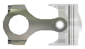 Shaded for inactive component set to On, with 50% opacity. 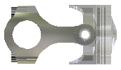 |
| Display Edges |
Sets the edge display for inactive components. When selected, displays edges of inactive models based on application or document appearance setting for model edges. If model edges use a single color, select a different color for inactive components to discern between active and inactive states. |
| Color | Activates the color picker. Specify the color for display of inactive model edges. |
Display
View transition time (seconds)
Controls the time required to transition smoothly between views when using viewing commands (such as Isometric View, Zoom All, Zoom Area, View Face, and so on). Zero transition time causes transition to be abrupt, which can make it difficult to understand changes in position and orientation. Three sets the greatest amount of time to transition between views.
Minimum frame rate (Hz)
Specifies the frequency for updating the display during interactive viewing operations such as Pan, Zoom, and Rotate. Some complex models (such as large assemblies with a high component count) may seem lower performing, changing the frame rate can improve the operation speed. Lower numbers show greater visual fidelity. To achieve higher frame rates, the system may temporarily simplify or discard parts of the view. The view restores when movement ends.
- Set 0 Draw everything in the view, regardless of the time required. Use this value for better visual fidelity. Increase the frame rate if the model updates too slowly during a viewing operation.
- Set 10 Draw at least ten frames per second. Use this value for a balance between visual fidelity and performance.
- Set 20 Draw at least twenty frames per second. Use this value for the fastest performance.
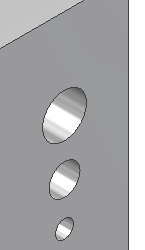
Display quality
Sets the resolution for the display of the model.
Display quality set to smooth.
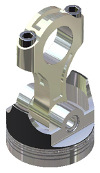
Display quality set to rough.
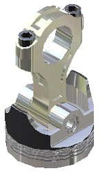
Display Quality set to smooth.
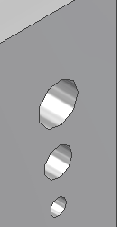
Display Quality set to smoother, and Maintain Enhanced Graphics Detail enabled.
Disable Automatic Refinement
Automatic refinement is enabled by default ensuring the appearance of Inventor faces and bodies is smooth when zooming. Select the check box to turn off automatic refinement and enable coarse faceting. Coarse faceting can increase performance in large assemblies or complex models. Use the Refine Appearance
 command in the View tab, or QAT, to smooth the appearance when Automatic Refinement is disabled.
Multiple Document Graphics
Automatically update referring documents
3D Navigation
Default Orbit Type
Changes the default behavior of the Orbit command.
Free Orbit behavior is relative to screen.
Constrained Orbit behavior is relative to model.
Zoom Behavior
Check or clear either checkbox to change the zoom direction (relative to mouse movement) or the zoom center (relative to the cursor or screen).
- Selected Mouse cursor moving upward in the display zooms in. Rolling the mouse wheel toward the display zooms in.
- Cleared Cursor moving upward in the display zooms out. Rolling the mouse wheel toward the display zooms out.
- Seleted Zoom operates with respect to the center of the display.
- Cleared Zoom operates with respect to the cursor position.
Sensitivity
- Slower Decreases the speed (graphic refresh frame rate) when zooming in and out.
- Faster Increases the speed when zooming in and out.
ViewCube... Opens the ViewCube Options dialog box, where you can define the display and behavior of the ViewCube navigation command.
SteeringWheels... Opens the SteeringWheels Options dialog box, where you can define the display and behavior of the SteeringWheel navigation command.
Origin 3D indicator When selected, turns on the display of the XYZ axis indicator and direction labels at the bottom left corner of the graphics window.
Show origin 3D indicator When selected, in a 3D view, displays an XYZ axis indicator in the bottom left corner of the graphics window. Red arrow indicates the X axis. Green arrow indicates the Y axis. Blue arrow indicates the Z axis.
Show origin XYZ labels When selected, displays XYZ labels on the arrows of the respective 3D axis indicator directions. Selected by default. Available when Show origin 3D indicator is turned on.
Look at behavior
Perform minimum rotation
Rotates a minimum angle to make the sketch plane parallel with the screen, and the x axis of the sketch coordinate system either horizontal or vertical.
Align with local coordinate system
Orients the x axis of the sketch coordinate system to be horizontal and right positive, and the y axis to be vertical and up positive.
Middle Mouse Button
Click the drop-down arrow to map the middle mouse button to zoom, pan, or orbit.
Use nearest model point for Orbit
When selected, the model point nearest the cursor is used as the orbit pivot point. Deselected, the center of the model minimum bounding box.