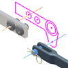
You can create assembly constraints between sketch geometry and geometry on other components.
Lines, circles, points, and their vectors can be incorporated into constraint schemes. Sketch behavior is like any other component used in an assembly: it can be adaptive, is previewed before a constraint is placed, and can be edited in the assembly.
To begin, do one of the following in an assembly file:
- On the ribbon, use Assemble tab
 Component panel
  Place to insert one or more components and a part file containing sketch geometry.
 - On the ribbon, use Assemble tab
 Component panel
  Create to create the components and part file with sketch geometry within the assembly.
To constrain a component to sketch geometry:
- On the ribbon, click Assemble tab
 Relationships panel
  Constrain
  .
. - In the dialog box, click the button for the type of constraint you want to add.
- Click First Selection, and then select the first face, curve, plane, or point.
- Click Second Selection, and then select the geometry to constrain to the first selection.
- Select the Solution for the constraint.
- Enter an offset, if applicable.
- Observe the previewed constraint. If either the component or sketch are adaptive, a constraint is not previewed.
- Click Apply to continue placing constraints or OK to create the constraint and close the dialog box.