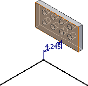
 In the tube and pipe assembly, if any existing geometry such as vertices, linear geometry, planar faces, and work features including work point, work axis, and work plane can help navigate through the route system, include them using the Include Geometry command and apply appropriate geometric constraints and dimension constraints to assist in the design.
The reference geometry is associative to the source geometry. Once it is used to constrain the route sketch, the route sketch can hence respond to changes to the source geometry. The reference geometry can only be used in the route in which it has been introduced. It does not participate in populating routes.
In addition, the reference geometry is automatically included when:
- A route starts by picking up an existing vertex or circular edge. A reference work point is included automatically.
- Some other route commands such as Parallel With Edge and Perpendicular commands are applied on existing geometry for forward creation
How is reference geometry represented?
All reference geometry within a route is grouped into the Included Geometry folder in the Model browser. When an inclusion in the route environment generates a work point, work axis, work plane, or reference edge, a corresponding browser node is added. Each type of reference geometry represents an adaptive symbol (![]() ).
).