When you open a drawing file, it opens with a default sheet containing the border, title block, and other elements specified in the template.
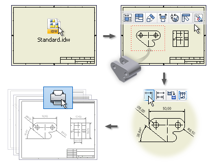
To create a drawing, you open a template, format it as desired, create drawing views, and add annotations. When finished, you can print the drawing.
Defining a Drawing Template
You can use any predefined template, or a custom template that incorporates conventions and standard elements.
Standard drawing templates are installed with Autodesk Inventor. During installation, you specify which standard to use as the default. Your selection adds the appropriate default drawing template to the Templates directory.
The default template is Standard.idw, which you can customize.
You can format the drawing by customizing sheet, border, or title block formats, and editing the drafting standard and annotation styles.
Specifying Drawing Views
Start by specifying a base view. Select a part or assembly file for the view, and specify a design view representation if the file is an assembly. You can create views of multiple parts or assemblies in the same drawing.
In an assembly, turn off visibility of those components that should not be seen in a drawing view. Save the simplified view in a design view representation and use it to generate uncluttered drawing views.
If your sheet format includes predefined drawing views, views are added automatically.
Adding Drawing Annotations
After placing views, you add annotations. You can use the model dimensions defined in the design phase or add drawing dimensions that serve as annotations but do not alter the model. You can change model dimensions from the drawing, if that option was selected when Autodesk Inventor was installed.
A drawing sketch is a special form of annotation. In Inventor, it acts as an overlay view to a drawing sheet. After you close a sketch, you can add drawing dimensions and associate symbols to the sketch geometry.
Printing a Drawing
You can print all or just part of your drawing. You can print IDW, 2D DWF, and DWG files.Model iProperties in Drawings
You can copy values of selected model iProperties to the drawing iProperties on the first view creation. Model iProperties are copied and updated in the drawing from a source model.
The Additional Custom Model iProperty Source option in drawing Document Settings lets you make custom iProperties from an external file available in the drawing.
About the Drawing Browser
The drawing browser displays drawing resources, drawing sheets, drawing views, referenced models, and objects placed on drawing sheets.
Sheets are arranged in the order of creation. You can expand a sheet to display its views and the parts that comprise the view. To change the order of a sheet, drag it to a new position in the hierarchy.
Only one sheet is active at a time. All other sheets are shaded in the browser. To activate a sheet, double-click its name.
- Drawing Resources. Shows the sheet formats, borders, title blocks, and sketch symbols that are available in the drawing. (Sketch Symbols also shows the sketch symbol definition.) You double-click a drawing resource to add it to a drawing sheet.
- Sheets shows the sheets in the drawing. The border, title block, and views on a sheet are listed under the sheet name in the browser. The displayed sheet is highlighted, all other sheets are shaded in the browser.
- Views. Shows the views on each sheet in the browser.