Quickly place holes using presets, or specify the hole dimensions, drill point, termination, and thread type options using the property panel.
What's New: 2019, 2019.1, 2020.1, 2020.2 2021, 2021.1
- The Property Panel workflow is progressive and flows from top to bottom of the panel. Parameters in a section affect the feature and set the context for the following sections in the panel.
- Property panels use a breadcrumb for steps in the process. You can click breadcrumb text to move to that step of the process. For example, during hole creation, if you click the breadcrumb "Sketch" you are placed in the sketch environment. If you click Hole, you are in the place feature environment. You can rename features and sketches through their breadcrumb.
- Rename active Hole and Sketch nodes from the property panel by clicking the breadcrumb text to select it, then clicking again to edit the text.
- Parameter values can be edited in the property panel, in-canvas, or by clicking-dragging the feature
parameter manipulator. Active manipulators highlight in the canvas, and in the property panel the associated field has focus.
- Edited values in the property panel can be committed by pressing Enter or Tab to move to the next field. Press Ctrl+Enter to create the hole and close the property panel.
- Value Edit visual feedback, when a value is invalid, for example, the specified thread length is larger than hole depth, the value color turns red. When a value is valid, the value color is black.
- To use existing parameters, dimensions, when positioning holes click the dimension option arrow and choose Select Feature Dimension.
- Reference dimensions, non-editable, are displayed inside parentheses.
- When editing a sketch, use commands that create, project, or duplicate hole centers.
- Preview controls
 are provided during both feature and sketch editing.
- The property panel experience is the same whether working in a part or assembly model.
- Legacy hole features created using the Linear placement option, when migrated, have a sketch with points and constraints created.
- For sheet metal parts, the default hole depth for Distance is the Thickness parameter.
Steps to create holes
- Click
3D Model tab
 Modify panel
Hole
Modify panel
Hole
 .
.
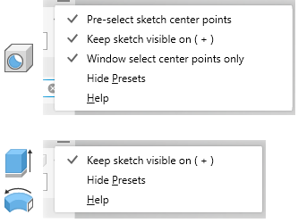
- Optional - check the panel menu to see if the options you want are active. The two options are:
-
Preselect sketch center points - causes all unused sketch center points, in the active sketch, to automatically be selected for use by the Hole command, populating each center point with a hole. Use Ctrl+click to remove center points from the selection set. Clear the option to disable pre-selection.
- Keep sketch visible on ( + ) - when using the Hole command, if unused sketch center points exist when you click
 (Create new hole), the sketch is automatically shared and visible for use with creating the next Hole. If you do not use the sketch for the next hole or click Cancel or Esc, the sketch will be unshared. You can share a sketch manually by right-clicking the sketch browser node and clicking Share Sketch. This option is available only in the Part environment.
- Window select center points only - by default the setting is ON and window select captures only center point objects. If you want to select any type of point object, which is the legacy behavior, click to turn the setting OFF.
-
- Specify a preset. If there are no presets or the preferred one doesn't exist, continue the process specifying the needed hole parameters.
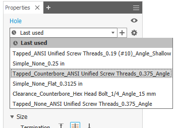 Note: When finished specifying the parameters and click OK, a preset named Last Used is created automatically. You can continue to use the preset or save it to a specified name. Tolerance values on hole parameters are saved in the preset.Important: If you want to create a preset, and the option is disabled, then, the HoleCmd.preset file is set to Read-only. Navigate to %USERPROFILE%\AppData\Roaming\Autodesk\Inventor xxxx\Presets folder. Right-click the preset file and click Properties. On the General tab, in the Attributes section, deselect Read-only.
 -
Specify the Positions. An existing sketch is not required. Valid inputs for hole locations include a face, sketch point (end or mid), or work point. You can limit the selection to existing points by turning OFF the Position option
 Allow Center Point Creation. The last used state the option was in is remembered for the next hole.
For example, if you toggle Allow Center Point Creation off to select line endpoints as hole positions, it remains off and does not automatically reset.
The Status bar, in the lower left corner, keeps you aware of the active command.
Note: Allow Center Point Creation is disabled when the Input Geometry > Position is a work point.- ON (default), you can add center points randomly on a part face.
- OFF, you can only select sketch center points, sketch points in an existing sketch, or work points.
When Allow Center Point Creation is
Clicking a face selects the body associated to the face, creates a sketch, and places the hole center. Clicking a point places the hole center, then, you select a face, plane, or linear edge to define hole direction. Clicking a workplane creates a sketch on the plane and places a hole center.
To edit the sketch, use the breadcrumb access at the top of the property panel. If a sketch with more than one hole center is visible, all hole centers without an associated hole are selected.
Tip: If your design workflow uses one sketch with many hole centers for holes of various sizes, you can quickly deselect all selected hole centers using the Clear Selections button at the end of the
Positions list in the
Input Geometry section.
at the end of the
Positions list in the
Input Geometry section.
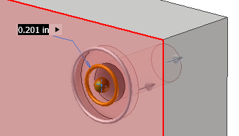
- Specify the hole position by:
- Clicking anywhere on a planar face or workplane. The hole center is placed where you click. You can drag unconstrained hole centers to reposition them.
- Selecting a point, and then, a linear edge (parallel to hole axis) or face/work plane (perpendicular to hole axis).
- Click a reference edge to place dimensions. Linear placement dimensions can be selected, edited, or deleted while you are in the Hole command. Select the dimension and change the value or use the Delete key to remove the dimension.
Note: To utilize existing sketch dimensions, when editing a dimension, click the dimension you want to utilize.
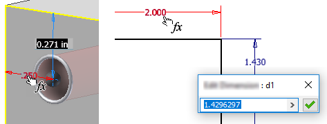
You can also click the arrow at the right end of the dimension field and choose Select Feature Dimension. Select the feature containing the dimension you want to use and then the actual dimension.
- To create concentric holes, place the hole center and click the model edge or curved face the hole is to be concentric with.
Note: You can select a workplane edge, then a model edge or curved face to place a concentric hole center. Hole depth is measured from the workplane.
- To remove a hole center from the selection and retain it in the sketch, use Ctrl+click and select the hole center. To remove the hole and hole center, select and delete the hole center point.
- To clear the selection, use the
Clear Selection button
at the end of the selected item.
Positions
- If there are two or more solid bodies in the part file, click the Solids selector to choose the participating solid bodies.
Solids
- Specify the
Type. A Type consists of: the Seat Type and the Hole Type.
 Simple hole creates a plain hole without a thread. No additional settings are needed.
 Clearance hole creates standard, untapped (and usually through) holes that are matched to specific fasteners. Use them to create clearance holes for standard fasteners based on a library of standard fastener data.
Note: Fastener information can be included in hole notes in drawings.
Clearance hole creates standard, untapped (and usually through) holes that are matched to specific fasteners. Use them to create clearance holes for standard fasteners based on a library of standard fastener data.
Note: Fastener information can be included in hole notes in drawings.To manage clearance data, Autodesk Inventor uses the Clearance.xls Microsoft Excel spreadsheet file, which is located in the Design Data folder. The Application Options or project settings affect the location of the spreadsheet file. You can change the order in the file so that the clearance you use most frequently is presented first. Edit the clearance spreadsheet and change the sort order number (from 1 to n) in cell B1 of each sheet to match your priority. To activate the new sort order, restart the program
 Tapped hole creates a hole with a thread that you define. Specify tapped holes in either English or Metric standard sizes. For part hole features you can select a common thread size from a list and its diameter is calculated.
 Taper Tapped hole creates a hole with a taper thread that you define. Specify the thread type and size and right-hand or left-hand direction, and Autodesk Inventor automatically determines the diameter, taper angle, and thread depth. Specify taper tapped holes in either English or Metric standard sizes.
Hole Type
 None is used to define a simple drilled hole. It has a specified diameter and is flush with the planar face.
 Counterbore holes have a specified diameter, counterbore diameter, and counterbore depth. You can’t use a Taper Tapped Hole with Counterbore.
 Spotface holes have a specified diameter, spotface diameter, and spotface depth. Measurement of the hole and thread depth starts from the bottom surface of the spotface. In a part file, you can specify zero (0) as a value for the bore depth on spotface holes. Thus, you can place a spotface hole on the termination face of a body.
 Countersink holes have a specified hole diameter, countersink diameter, countersink depth, and countersink angle.
Seat Type
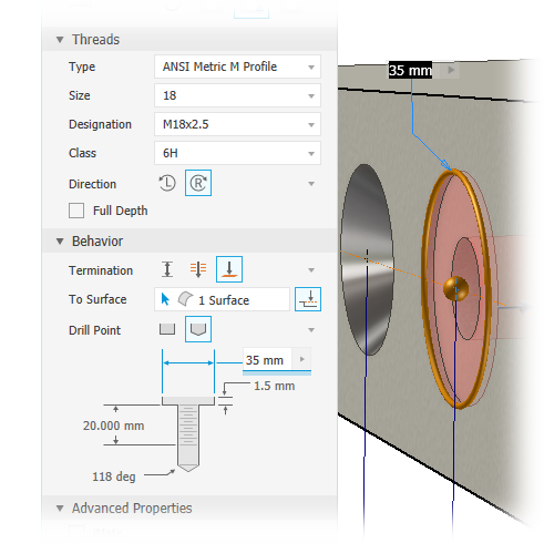
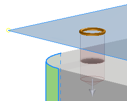
- Specify the hole Termination options:
 Distance defines the termination method for the hole. Uses a positive value for the hole depth. Measures depth as perpendicular from the planar face or workplane.
 Through All extends a hole through all faces.
 To terminates a hole at the specified planar face. Select the surface on which to end the hole termination.
- Click the Surface select button to terminate the hole on a selected surface or face.
- If Off, check
Extend To when the termination face or body does not intersect with the hole feature.
Note: The default setting for Extend To is on.
 Direction 1 (default) specifies the hole direction as going into the selected face.
 Direction 2 reverses the hole direction.
 Symmetric is available only for the Drilled - Simple Hole - Through All hole type. It creates a symmetric hole type that extrudes in two directions.
Direction
Direction is available when using Distance and Through All termination options.
-
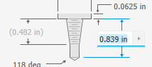
Drill Point
 Flat creates a flat drill point.
-
 Angle creates angled points, on the drop-down list, specify angle dimension, or on the model, select geometry to measure a custom angle, or show dimensions. The positive direction of the angle is measured counterclockwise from the hole axis, normal to the planar face.
Termination
-
Threads enables when the Tapped or Taper Tapped hole type is selected. Specify the hole parameters:
- Type specifies the thread type. Select from the list of standard threads.
ANSI Unified Screw Thread is an example of an inch-based thread type. ANSI Metric M Profile is an example of a millimeter-based thread type. NPT is an example of an inch-based thread type. ISO Taper Internal is an example of a millimeter-based thread type.
- Size specifies the thread size. Select from a list of nominal sizes for the selected thread Type.
Each nominal size has one or more pitches available. Each nominal size and pitch combination has one or more classes available.
-
Designation specifies the thread pitch.
Pitch is the distance from a point on a screw thread to a corresponding point on the next thread measured parallel to the axis.
Note: If you use imperial units, the pitch is equal to 1 divided by the number of threads per inch. -
Diameter displays the diameter value for the hole feature type. This value relates to how drawing views represent the threads.
To change this value go to Tools
Options Document Settings Model tab. Change the Tapped Hole Diameter value. The hole diameter is set automatically based on the thread specification in the Thread.xls.
- Class specifies the class of fit for the internal thread.
Note: For English threads, the letter A represents external threads, and B represents internal threads. Use higher numbers for more accurate, closer fitting requirements. For instance, use 2B for screws, bolts, nuts, and other general applications. Use 3B for highly accurate and close-fitting requirements.
- Full Depth specifies threads for the full depth of the hole and can only be specified for tapped holes.
- Direction specifies how the threads wind.
 Left Hand, the threads engage in a counter clockwise and receding direction when viewed perpendicular to the hole axis. A left-hand threaded bolt advances into the nut when turned counter clockwise.
 Right Hand, the threads engage in a clockwise, receding direction when viewed perpendicular to the hole axis. A right-hand threaded bolt advances into the nut when turned clockwise.
- Type specifies the thread type. Select from the list of standard threads.
-
Fastener enables when the Clearance hole type is specified.
- Standard specifies the fastener standard. Select from a list.
- Fastener Type specifies the fastener type. Select from a list.
- Size, selects the fastener size from a list.
- Fit, specifies the clearance hole fit (Normal, Close, or Loose) relative to the selected fastener.
-
Advanced Settings are additional options that include:
- iMate: Select to place an iMate automatically on the hole being created. To learn more about iMates see iMate Fundamentals.
-
Extend Start: Select to extend the start face of a hole to the first place where there is no intersection with the target body. Extend Start removes a fragment resulting from the creation of the hole. If the result is not desired, deselect Extend Start to undue the result.
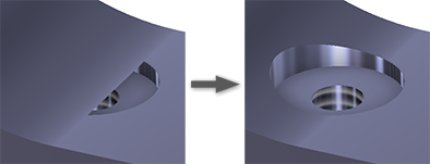
Note: For multibody parts, Extend Start does not extend into a secondary body. An exception to this behavior occurs when the secondary body intersects with the hole body volume being removed. The intersection area is removed. - Click
OK, or to create another hole with the current definition, click
Create new hole
and continue using the Hole command. You can use
Ctrl+Enter instead of clicking OK.
Editing Hole Features
- Double-click the feature node.
- Right-click the feature node and select Edit Feature.
In the model browser, edit a hole feature by doing one of the following:
The property panel displays and you can modify the Hole feature parameters.
Need another hole? Click the Sketch breadcrumb text, add a hole center, then, click the Hole breadcrumb text and the hole is added.
Value fields display in the property panel and in the Edit control in-canvas. Either can be used to specify the dimension value or the equation to use for the value. You can also edit the parameters in the canvas or graphics area. When you are editing a hole dimension using keyboard input you can switch to using the mouse and manipulators without having to click another command to select the manipulator.
- Measure - activates the Measure command and uses the measured value as input to the field.
- Select Feature Dimension - click the feature that has the dimension you want to use, then select the dimension you want to use. The selected dimension parameter is assigned to the value field.
- Tolerance... - displays the feature Tolerance dialog for your use.
Delete Hole Features
-
In the model browser, right-click the feature node and select Delete.
- Set Selection to Feature Priority and select the hole feature.
To delete a hole feature do one of the following:
If desired, continue to make selections in the Delete Features dialog and click OK.
Edit Feature and Sketch Names Using the Breadcrumb
- Click the breadcrumb text you want to edit to activate the text.
- Click the text again to enter Edit mode.
- Modify the text.
- Press Enter to commit the change.