You can create corners during the creation of flange and contour flange features.
These corners display the default corner relief shape when the model is displayed as flat. In certain cases, the created flanges can automatically miter when they would otherwise interfere. You can override the corner relief shape during the creation or edit of the feature, and display a glyph in the graphics window when this option is available. Not all corners provide the glyph edit option.
The following images show a model, and then the model with a flange added to the top edges:
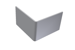
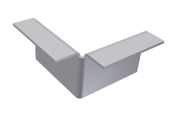
The outside radius of this added flange is on the opposite side of the outside radius of the bend between the two selected edges. This condition does not offer an edit glyph during creation or edit.
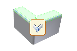
However, if you start with the same initial model condition and create the flange in the opposite direction, your model appears as the following image:
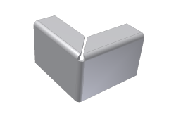
In this case three bends converge upon the corner and their outside radii are on the same side as the outside radius of the bend between the selected edges. This condition provides an edit glyph during creation or subsequent edit as follows:
If the default bend, corner or unfold settings are not appropriate, you can override the values for an individual flange feature using the Unfold Options, Bend, or Corner tab as required.