What's New: 2022
When using Export to RVT the first step in the process is to use the integrated Simplify command to remove unnecessary components and features from the assembly.
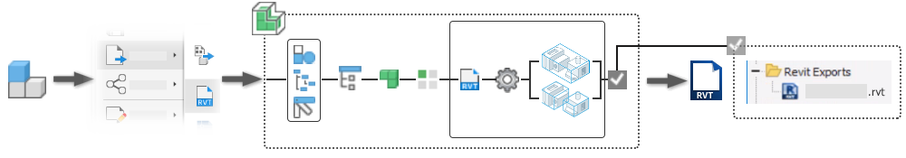
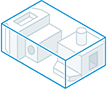
Exporting an RVT model
- In the
File menu
 Export click
Export to RVT. The Simplify property panel displays.
Export click
Export to RVT. The Simplify property panel displays.
The Simplify command is used to both create and edit simplified parts. Legacy simplified or shrinkwrapped parts use the Simplify property panel when edited.
- Optionally, select a built-in preset to use. Four built-in presets are provided, plus you can create your own.
- Remove the least detail (small parts and features) - the settings are designed to remove small parts and features, resulting in the most detailed model.
- Remove moderate detail (medium sized parts and all listed features) - the settings are designed to remove a moderate amount of detail.
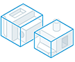
- Remove the most detail (replace top-level components with envelopes) - the settings are designed to remove the greatest amount of detail resulting in very basic shapes.
- No Simplification - the simplified version is full fidelity with respect to the assembly model. All details are visible in the model.
Tip: Select a preset close to what you want for detail, then use View Included and View Excluded to quickly select the remaining parts. This expedites the process.The same method can be used for creating your own presets. For more information see To Work with Presets.
- The following are the Simplify steps to produce RVT output.
- The
Input group fields populate with the current state of the assembly. You can change them as needed.
- Model State. Defines the envelope size. Changes in a model state affect the envelope size.
- Design View. The active design view displays. Changes in design views do not affect envelope size.
Click the
 Associative option to link the design view with the simplified model. The option is not available with the [Primary] design view.
Note: When Associative is selected, the Components group is not available. Component changes come from the design view.
Associative option to link the design view with the simplified model. The option is not available with the [Primary] design view.
Note: When Associative is selected, the Components group is not available. Component changes come from the design view. - Position View. Helps define the envelope size. Changes in position view can affect the envelope size.
- Replace with Envelopes provide the means to replace components with simple rectangular shapes. When you click on an option, preview shows the parts represented as envelopes.
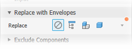
 None - select this option when you are not using envelopes for the simplification. Components and Features groups are available for use.
 Top Assembly - creates an envelope around the top-level assembly. The result is imprecise and useful for developing a "keep out" area for the design. When this option is selected the Components and Features groups are hidden.
 Top Components - creates an envelope around assembly first-level components. Component selection tools display. Feature selection tools are hidden.
 All Parts - creates envelopes for all parts in the assembly. Feature selection tools are hidden.
The choices are:
- Exclude Components - provides tools for selecting parts and components to include in or exclude from the simplified part. You can:
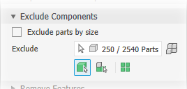
- Remove parts by selection (default). Remove parts by size is deselected.
- Remove parts by selection (default). Remove parts by size is deselected.
- Click the selection priority you want to use. Choose either
 Part Priority or
 Component Priority.
- To select all occurrences of the selected item click the
 All Occurrences option.
- Click the selector and begin selecting parts or components in the canvas. When active, the selector has a blue highlight at the bottom of the selector.
- Click the selection priority you want to use. Choose either
- Click the selector and begin selecting parts or components in the canvas.
- Remove parts by selection (default). Remove parts by size is deselected.
- Exclude parts by size
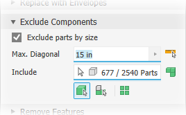
- Select the Exclude parts by size option.
- Specify the maximum diagonal value for a bounding box. Parts or components that fit inside the bounding box are removed. Use one of these methods to specify the size:
- Enter the value in the Max. Diagonal edit field.
- Click the arrow at the end of the value field to select a recently used value.
- Click the measure diagonal bounding box button
 then select a part/component to supply the diagonal value.
- Click the selection priority you want to use. Choose from
- Part Priority
- Component Priority
To select all occurrences of the selected item click the
All Occurrences option.
- Auto-detect locates and highlights the components.
- Continue selecting remaining components as needed to exclude them from the simplified part.
- Click
 View Excluded to display the components being removed or
 View Included to see the components that are included in the simplified model.
- Remove parts by selection (default). Remove parts by size is deselected.
- Remove Features provides options for selecting features by type or size to include in or exclude from the simplified part. The list of features include holes, fillets, chamfers, pockets (subtractive), embosses (additive), and tunnels (single and multiple entry). Internal voids are automatically removed.
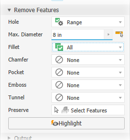 For each of the listed feature types specify which you want to remove and the way you want to remove them:
 None (default) - no features of this type are removed.
 All - all features of this type are removed.
 Range - all features equal to or smaller than the specified parameter are removed. Specify the value that defines the maximum size to remove.
- Preserve - click the selector and select the features you want to retain from those being removed.
Note: The rules for feature recognition are minimal allowing for crossover, for example, holes also meet the definition for tunnels. Thus, some holes outside of a range may be removed as Tunnels. To resolve this, you can click Preserve and select any feature you want to remain in the simplified part.
 Highlight applies a color to the features to be removed.
- Output provides options to define the output type and structure for your intended use.
- Type
- Revit Model File (RVT) - outputs your Inventor design as a Revit model so you can provide it to building designers or other downstream uses.
Model orientation: The export process looks at the Inventor ViewCube Top and the Inventor Y-axis. If the Y-axis is perpendicular to the Top plane, the model is rotated so the Inventor Z-axis is perpendicular to the View Cube Top plane.
- Revit Model File (RVT) - outputs your Inventor design as a Revit model so you can provide it to building designers or other downstream uses.
- Name - use the default file name or specify your own. The default uses the assembly name and adds a suffix.
- Location - Sets the location of the new file. To find the part when the assembly is opened, specify its directory by a path in the project used for the assembly.
- Structure - available for RVT only, choose the desired Structure options:
- All in One Element
- a Revit model with one element representing the simplified assembly is output.
- Each Top Level Component - a Revit model with multiple elements representing the first level components of the simplified model.
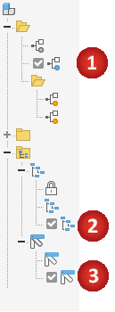
- Enable updating - creates a browser node that enables you to edit the simplification and update the exported RVT. This option is selected as a default. If deselected, no browser node is created and export criteria is not retained. Any updates to the exported file require exporting the model again.
Note: Select Enable updating if the Inventor design is expected to change as the exported RVT file can be updated by editing the simplified model.
- All in One Element
- a Revit model with one element representing the simplified assembly is output.
- Type
- Advanced Properties provides other settings that help manage the simplify output.
- Break Link to disable updates permanently and remove associativity between the parent assembly and the simplified part.
Note: Not available for RVT output.
- Rename simplified components. The following items are renamed:
Note: Not available for RVT output.
- The selected and all child browser nodes. The part renaming follows this pattern: "Part[sequence number]:[instance number]" which yields "Part1:1", "Part2:1", and so on. For part instances the instance number is iterated which yields "Part1:1", "Part1:2", and so on.
- The elements under the Solid Bodies or Surface Bodies folders. The element renaming follows this pattern: Surface body nodes are renamed "Srf1", "Srf2", and so on, and Surface feature nodes are renamed "Surface1", "Surface2", and so forth.
- The Assembly node is renamed to Assembly1.
- Remove internal parts selected by default. Inventor looks at the model from 14 standard directions (six orthographic and eight isometric) to determine a parts visibility state. Parts deemed not visible are removed.
- Use color override from source components to link color from the base component into the target part. If deselected, the appearance is set to default appearance of the target part.
- Make independent bodies on failed Boolean to create a multi-body part when a Boolean operation fails on one of the single solid body style options. Available only when Style is Single body with no visible edges between planar faces or Single body with visible edges between planar faces.
Note: It is possible to produce gaps when small faces are removed. If gaps are present, the result is a nonmanifold body.Note: Not available for RVT output.
These are the general settings:
- Break Link to disable updates permanently and remove associativity between the parent assembly and the simplified part.
- Click
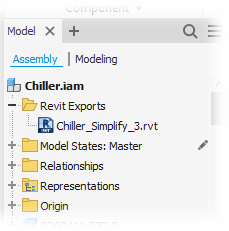
OK to create the RVT model from the specified criteria. The Inventor model browser populates with a folder called Revit Exports. The folder is populated with a node linked to the exported file.
 Note: The simplify definition is maintained in the Inventor Assembly, including the export location specified at RVT creation. If the RVT file has been moved or deleted, the simplify definition is used to recreate the exported RVT model in the initially designated export location. The moved file DOES NOT update.Important: It is possible to export nothing and get an export successful message. This can happen if all elements have been simplified out of the model or if the exported data is mesh and not solid. These conditions result in an empty RVT file.
Note: All internal voids are automatically filled.Imported Revit data is not included in the exported RVT model.
- The
Input group fields populate with the current state of the assembly. You can change them as needed.
Context menu commands for the RVT model node
- Right-click the RVT node and click
Delete.
Important: Only the node is removed from the assembly. The file still exists in the location folder. Removing a node means that future edits to the Inventor model will require exporting to a new RVT model.
Update
Update is an on-demand request that you initiate manually. The action pushes any changes to the Inventor model to the RVT model and does an incremental change. Preview is not available for updates, but the process progress displays.
- Expand the Revit Exports folder.
- Right-click the RVT model you want to modify and click Edit Simplify and the Simplify command activates.
- In the Simplify property panel, make the necessary edits.
- Click OK.
Related Export RVT Errors
- Error message: "This Revit model was created using an unsupported value for the 'Structure' option." This occurs when, from Inventor, the Edit command in the RVT browser node context menu is used. The exported RVT file was generated with a newer version of Inventor. The exported RVT file used a simplification structure option that does not exist in the Inventor version being used to open the file. For more information about the "Future" file message see Troubleshooting Design Errors and Messages.
- Export successful message from Inventor with a failed export message in Revit. It is possible to simplify all parts from an assembly and end up with an empty file. Mesh objects do not export to RVT. If only mesh objects are being exported, the RVT file is empty.