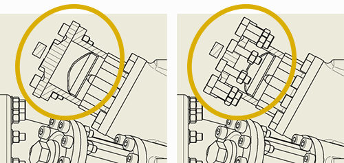
You can remove a defined area of material to expose obscured features in an existing drawing view.
To create a breakout:
- Select an existing view or place a view in the drawing.
- Break out views require an associated sketch with one or more closed profiles to define the boundary of the breakout area. The following describes what happens when:
- The selected view doesn't have a sketch - a view sketch is added and you are placed in Edit sketch mode. When the boundary is defined and you exit the sketch, the Break Out View dialog displays.
- The selected view has a sketch, but the profile is not closed - a message displays explaining the condition. You can respond with:
- OK - takes you into sketch mode where you can close the profile, then, click OK to return to creating the view.
- Cancel - terminates the Break Out view command.
- Help - brings you to this page.
- The selected view has multiple, non-closed profiles - a message displays explaining the condition. Click OK to exit the command. Then, select the desired sketch, close the profile, and repeat the Break Out view command.
- The Boundary is automatically selected unless there are multiple unconsumed sketches associated with the view, then you must select one.
- Specify the Depth of the break out. You can define the depth of the breakout area from a point in the model, in a sketch associated to a projected view, using a hole feature in a view, or by the depth of a part.
- Specify the display preferences. If you want to show components that are inside the cut volume, select
Components within the section cut.
- Click OK.
The active Standard and the Hatch style assigned to the Section Hatch object in Objects Default determines the default hatching in breakout views.
Specify a Breakout from a Point in the Model or a Sketch Associated to a Projected View
You can specify a starting point for the breakout area and measure the depth of the area from that point or by using geometry on a sketch associated to a dependent projected view.
- If you are specifying from a point in the model, project a view from the base view, create a sketch associated to the projected view, and add geometry to define the depth for the breakout.
- On the ribbon, click
Place Views tab
 Modify panel
Break Out
Modify panel
Break Out
 .
.
- In the graphics window, click to select the view, and then click to select the defined boundary.
Note: The boundary profile must be on a sketch associated to the selected view.
- In the Break Out dialog, click the drop-down arrow next to the Depth type box and select To Sketch or From Point.(If you select From Point, you can specify a number in the Depth field.)
- Click the select arrow, and then in the graphic window click to select either:
- The sketch geometry associated with the projected view. (You can specify the point in any view of the model.)
- The start point for the depth.
- If you are creating a breakout from a point in the model, in the Depth value box, enter the depth of the breakout.
Using a Hole Feature in the View or by the Depth of a Part
You can specify the depth for the breakout using a hole feature in the view or one or more parts to break out of the selected view to expose the obscured parts or features. The depth is defined by the axis of the hole or the depth of the part.
- On the ribbon, click
Place Views tab
Modify panel
Break Out
.
- In the graphics window, click to select the view, and then click to select the defined boundary. The boundary profile must be on a sketch associated to the selected view.
- In the Break Out dialog, click the arrow next to the Depth type box and select To Hole or Through Part.
- Click the select arrow, and then in the graphic window click to select the hole feature or part.
Note: If the hole feature is hidden, click Show Hidden Edges to show it temporarily.
- When the view is fully defined, click OK to create the view.