Various labels associated with result probes, min and max values, and mesh failures, present simulation information in the graphics area. You can change the initial distance at which labels are placed, drag labels, and reset the position of labels.
Define initial label placement
- On the ribbon Stress Analysis tab
 Settings panel, click Stress Analysis Settings
  .
. - On the General tab, change the Initial Label Placement Distance setting as a percentage of the diagonal of the model bounding box. Note: Changes to the setting do not affect the position of existing labels.
Move labels
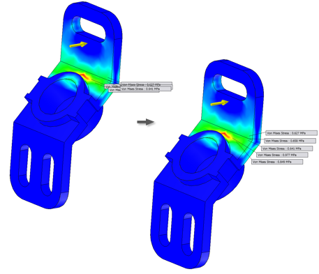
- In the graphics window, select one or more labels.
- Click one of the selected labels and drag to the new position.
To cancel the operation and return labels to their previous location, press ESC while dragging.
Reset labels to initial positions
- In the graphics window, select one or more labels.
- Right-click and click Reset Position.
To reposition all labels in the graphics window, right-click any label, and select Reset All Positions.
Note: To select a label positioned behind a part, change your selection filter to Select Sketch Features  , or rotate the view.