
Before you run a simulation, ensure that the mesh is current, and view it in relation to the geometric features of the model.
Integrity errors such as small gaps, overlaps, overhangs that are sometimes overlooked in models can cause trouble for mesh creation. In that case, recreate or modify the problematic geometric features.
Some spring models mesh when the long helical face is split by a cutting plane containing the axis
If the model is too complex and has geometric singularities, divide it into less complex parts that you can mesh independently. Use a bonded contact between them to make these components behave as a single part.
Use a finer mesh in troublesome areas that you cannot simplify. Decreasing the global mesh size, as well as the local mesh size on certain faces and edges, can help to create a successful mesh.
View mesh for simulation
- On the Ribbon: Stress Analysis tab
 Mesh panel, click Mesh View
  .
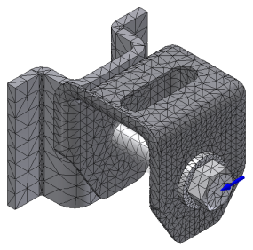
. The mesh generates as an overlay on the model geometry. The mesh count, nodes, and elements display in the corner of the graphic display. If simulation results are also visible, the node and element count visibility is managed with the Color Bar information. Thus, with results visible, when the Color Bar visibility is set to Off, the node and element count is also not visible.
You can accept the default mesh and proceed to the simulation, adjust the mesh settings, or use a local mesh control.
You can also use Mesh View to overlay the mesh on top of the simulation results to see where the stress concentrations are in relation to the mesh elements.
Adjust mesh settings for simulation
Mesh settings are established for each simulation, and apply to the component in a global sense. For Parametric Dimension simulations, one mesh setting applies to all parameter ranges.
- To view mesh settings, on the Ribbon: Stress Analysis tab Mesh panel, click Mesh Settings
 .
. - Specify the mesh settings. These parameters specify the mesh sizing and coarseness. Smaller mesh elements take longer to simulate.
- Average Element Size
- Specifies the element size relative to the model size.
Default 0.1
Recommended Between 0.1 and 0.05
- Minimum Element Size
- Allows for automatic refinement in small areas. The value is relative to the Average Size.
Default 0.2
- Recommended Between 0.1 and 0.2
- Grading Factor
- Effects the uniformity of the mesh transition between fine and coarse mesh. Specifies the maximum edge length ratio between adjacent element edges. For example, a setting of 1.5 limits an elements edge length to 1.5 times the edge length of the adjacent element.
Default 1.5
Recommended Between 1.5 and 3.0
- Maximum Turn Angle
- Effects the number of elements on curved surfaces. The smaller the angle, the greater the number of mesh elements on a curve.
Default 60 deg.
Recommended Between 30 and 60 deg.
- Create Curved Mesh Elements
- Creates meshes with curved edges and faces. When cleared, produces meshes with straight elements, which can be a less accurate representation of the model. Use a finer mesh in the stress concentration area around a concave fillet or round to compensate for the lack of curvature.
- Use part based measure for Assembly mesh
- In assemblies, sets part mesh sizes to be like the part based context (part outside the assembly context). Useful for assemblies composed of many parts of different sizes.
- After you change mesh settings, on the mesh node context menu, click Update Mesh.
- To see the updated mesh, click Mesh View.
Add a local mesh control
Sometimes a normal mesh size provides insufficiently detailed results for small or complex faces. You can adjust that meshing size manually to improve stress results in a local or contact area.
- In the browser, right-click the mesh folder node, and click Local Mesh Control
 .
. - Select the faces and edges to which you want to apply local control.
- Specify the mesh element size.
- Click OK.
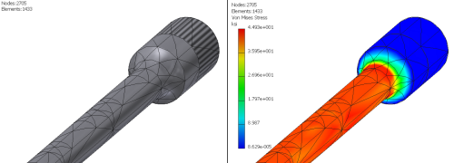
If you see a stress concentration, consider setting the mesh a little finer for the simulation. Mesh parameters apply to all components and model features.
Edit a local mesh node
- Right-click the local mesh node and click Delete, or Edit Local Mesh Control.
- You can change the mesh size or selected entities, faces, and edges contributing to the mesh.
- Click OK.