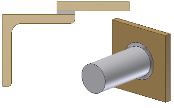
Creates a groove weld feature in a weldment assembly that connects two face sets with a solid weld bead. A welding symbol can be created simultaneously with the feature or it can be created in a separate operation.
The weld bead and welding symbol are separate features in the welds folder of the browser. There is no association between the welding symbol and the weld bead feature so you can specify any welding symbol values for the weld bead feature. When consumed by a welding symbol, the groove weld is a child node of the welding symbol.
- Access
- Right-click the Welds folder in the browser and select Edit. On the ribbon, click
Weld tab
 Weld panel
Groove.
Weld panel
Groove.
The Bead box specifies the parameters for constructing the groove weld.
- Face Sets 1 and 2
- Selects the two sets of faces to connect by a groove weld bead. Each face set must consist of one or more contiguous part faces.
- Full Face Weld
- Specifies how the weld bead appears for both face sets.
Clear the check box to specify that the weld bead ends at the extents of the smaller face set.
 Select the check box to specify that the weld bead extends to consume both face sets. If face sets 1 and 2 are different lengths, the weld bead expands to fit both faces.
- Chain Faces
- Selects multiple tangent faces.
- Ignore Internal Loops
- Determines if a selected face set results in a hollow groove weld or a solid weld.
Clear the check box to specify that the weld bead extends along the loop, but not the face.
 Select the check box to specify that the weld bead spans the internal loop to cover the entire face.
- Fill Direction
- Sets the direction in which groove weld face sets are projected onto one another when connected by the groove weld bead. To define the fill direction, you can select:
- Planar faces and work planes (specifies direction normal to the chosen face or plane)
- Cylindrical, conical, or toroidal faces (specifies direction of the surface axis)
- Work axes
- Part edges
- Two points (work axis, model vertex)
-

- Projects the weld bead at the angle of the first selected face set.

-

- Projects the weld bead perpendicular to the second selected face set.

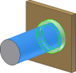
 Radial fill
- Projects the weld bead around a curve. Fill Direction is not available when the Radial Fill check box is selected.
Select Create Welding Symbol to expand the dialog box to set welding symbol parameters. Click this link to go to the Model Welding Symbol Reference.