You can create a contour flange, specify its dimensions, and create a multi-edge contour flange with auto-miter
You define a single contour flange by selecting an open profile. Inventor can create contour flanges along an edge or edge loop.
Inventor previews the flange material thickness along the selected profile and toward the material of the selected edge. However, you can reverse the thickness direction.
You can specify the extrusion distance for a contour flange that is a base feature. You can also specify a distance when the contour flange is longer than the selected edge, or when you cannot select an edge.
If the default bend, corner or unfold settings are not appropriate, use the Unfold Options, Bend, or Corner tabs to change the settings.
Create a Contour Flange
- Create a 2D open profile sketch.
- On the ribbon, click
Sheet Metal tab
 Create panel
Contour Flange
Create panel
Contour Flange
 .
.
- Click an open profile.
- If there are two or more solid bodies in the part file, click the Solids selector to choose the participating solid body.
- (Optional) If a body exists, click New Solid to create a new body.
- To change the direction for the thickness of the flange, click a selection in Offset Distance.
- (Optional) Do one of the following:
- Select the Follow Defaults checkbox to link the material thickness and rules to the Default setting.
- Clear the Follow Defaults checkbox and click the drop-list to specify a unique material thickness and rules from the predefined list.
- Do one of the following:
- To create a contour flange around an edge loop, click Loop Select Mode, and then select an edge loop on a plane that is perpendicular to the profile sketch plane.
- To create a contour flange along edges, select edges.
- In Bend Radius, specify a value.
- In Extents, specify an extrusion distance.
To set the extrusion direction relative to the profile sketch plane, click a Direction.
Specify the Width Extents
After you start the contour flange command, you can use options to specify the flange width using From To, Offset, Width, or Distance values.
- In the Contour Flange dialog box, click More.
- On the Extents Type drop-down list, click From To, Offset, Width, or Distance. (Clicking From To selects the start and end vertices of the edge automatically.)
- Click Offset1, and then do one of the following:
- To specify From To values, select model geometry that defines the beginning location of your flange.
- To specify Offset or Width values, select a work point, workplane, or face from which the flange is offset. When defining extents, you can select planar faces that intersect the base face edge.
- To specify Distance values, enter a value and modify the distance Direction relative to the plane of the profile sketch as required. (The plane of the loop selected for your contour flange must be perpendicular to the profile sketch plane.)
- Click Offset2, and select model geometry that defines the ending location of your flange.
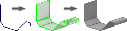
Create a Multi-edge Contour Flange with Auto-miter
Auto-mitering has contour flanges that share a common corner automatically show a full or partial miter. You can modify any of the contour flange parameters.
- On the ribbon, click Sheet Metal tab Create panel Contour Flange
.
- On the Contour Flange dialog box Corners tab, select Apply Auto-Mitering.
- At the prompt, select an edge. Select multiple edges to generate flanges using values that you enter.