About Boundary Patches
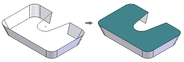
The Boundary Patch feature generates a planar or 3D surface from a closed 2D sketch, a closed boundary, or a mixture of both. The patches default to contact (G0), but can have edge conditions of tangent (G1) or smooth (G2) applied to each model edge.

Alternatively, you can select one or more closed 2D or 3D sketches to form a nonplanar patch. When a closed sketch is selected, the corresponding region is highlighted in the graphic window. Once the region is highlighted, you can use Select Other to select specific geometry within the sketch.


For all selection methods, the OK command is enabled once a closed loop is defined so that you can select more loops. By selecting more loops, you can define inner and outer loops that make islands in the surface. If a planar region is selected, selection of extra loops is not allowed.
Tips for creating boundary patches:
- If you create a boundary patch with tangent constraints, avoid using supporting faces that are all perpendicular to one single imaginary plane. An angle that is not 90 degrees is expected.
- Avoid creating a boundary patch on construction geometry that consists of a single segment closed curve (circle, ellipse, or closed spline).
- For best results, stitch boundary patches to adjacent surfaces before creating features, such as sculpt, shell, and thicken/offset.
About Stitching Surfaces
In the part environment, you can use the Stitch command to stitch several edge-matched surfaces together to create a quilt. This operation is parametric; changes to the parent surfaces update the quilted surface.
Surface edges must be touching to be stitched. The Stitch command has a tolerance control that provides an upper limit and helps to determine which edges to stitch.
About Ruled Surfaces
The Ruled Surface feature creates surfaces that extend the specified distance and direction from selected edges. Ruled surfaces are often used in casting design to create parting surfaces or to create smooth extensions to complex surfaces. Specify the type to achieve the desired results.
- Use the Normal option to create a surface normal to the selected edge.

- Use the Tangent option to create an extension that maintains the tangency curvature.

- Use the Vector option to specify direction by selecting a face, work plane, edge or axis.
