Options for managing the relationship between representations and drawing views, to achieve various process benefits.
What's New: 2022
Model state, design view, and positional representations are created in the assembly environment and preserve an assembly state. When you create a drawing view of an assembly, you can select any combination of model states and representations that are defined in the assembly.
Model States and Positional representations are associative to the drawing view. You can also create an association between a view representation and the drawing view by checking the Associative box. If you make a drawing view associative to a view representation, the drawing view updates automatically when changes are made to the assembly.
Guidelines for creating views
- Model State, Design View, and Position View representations must be created in the assembly, not the drawing.
- Invisible components in a design view representation are shown in the drawing browser, but are not computed in a view.
- Suppressed components in a model state do not participate in the Parts List, do not appear in the drawing browser, and are not computed in a view.
- Drawing views are associative to the selected model state and positional representation and update automatically. A design view updates automatically if the Associative box is checked.
- Design View Representations that designate components as transparent affect associative drawing views. In such views, the model transparent setting has precedence over the drawing view transparency setting.
Guidelines for Creating and Maintaining Annotations
- Annotations that have their references suppressed are deleted, unless you set an option on the Drawing tab of the Document Settings dialog box to preserve orphaned annotations.
- You can create general annotations only to unsuppressed components. If an annotation is sick because its reference is suppressed, the annotation is deleted, or you can redefine it to point to a new reference.
- A parts list for a migrated Level of Detail always references the Primary model state.
- Suppressed components in a model state are not reflected in a parts list.
- Balloons are created only for unsuppressed components. If you change a model state so that the balloon references a suppressed component, the balloon is deleted.
- Hole tables do not show information for components that are suppressed in a view.
- Hole notes attached to a component that becomes suppressed are deleted.
Use Design View Representations to Improve Performance
- Do any of the following to take advantage of performance benefits and memory savings:
- Select a design view representation that only displays the components that must be visible. Invisible components are included in the parts list but are not computed in the drawing view.
- Close the assembly file used for a drawing view to prevent its graphics from being loaded into memory.
- To edit the model displayed in the drawing, in the Application Menu, click Open to select the assembly file, and then click Options. Select the representation used in the drawing.
Create Drawing Views Using Assembly Positional Representations

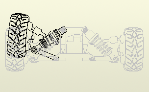
Positional representations capture a kinematic "snapshot" of an assembly to show components in various configurations. Multiple positional representations can be saved in an assembly. You can specify a positional representation by name when creating a base drawing view. The created view is associative to the positional representation, and updates automatically.
- Create or open a drawing.
- On the ribbon,
Place Views tab
 Create panel
 Base.
Base.
- In the Drawing View dialog box, select a model file.
- On the Component tab, select a Positional Representation from the Position list.
- Set other options in the Drawing View dialog box and click OK.
Change the Design View Representation for a Drawing View

When you create a drawing view of an assembly, you can select any of the design view representations defined in the assembly. You can also create an association between the design view representation and the drawing view by selecting the Associative check box.
The design view representation for a drawing view, and the relationship between them, can be changed after the view has been placed.
- Right-click a drawing view and click Edit View.
- In the Drawing View dialog box, change the design view representation.
Create Drawings of Parts and Assemblies Using Model States
Use a Model State when creating a drawing to document different part and assembly representations.
When creating a drawing view, you can select a Model State. Suppressed components in an assembly are not included in the parts list or computed in the drawing view.
After the view is created, you can edit the drawing view and select a different Model State.
- On the ribbon, click
Place Views tab
 Create panel
 Base.
Base.
- In the Drawing View dialog box, select the model file.
- Select the Model State to represent in the view.
- In the Drawing View dialog box, specify other settings, and click OK.