What's New: 2019.1, 2019.2, 2020.1, 2021, 2021.1
Edit the standard, family, size, material, appearance, and orientation in the context of the assembly where the frame member resides.
Start in the assembly environment with an assembly model built previously in Frame Generator.
-
 On the ribbon, click
Design tab
On the ribbon, click
Design tab  Frame panel
Change.
Frame panel
Change.
- Optionally:
 Select a saved Preset to configure the frame member.
-
 Expand the Advanced Settings Menu in the upper right corner of the panel.
Note the checked defaults and make any required changes to the settings.
-
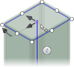
 Select the frame members to change in the graphics display.
Note: The radio buttons and manipulator arrows display where you click.
Select the frame members to change in the graphics display.
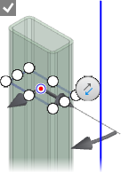
Note: The radio buttons and manipulator arrows display where you click. - After you select Input Geometry, use the display controls to set the zoom and view orientation.
 Sets the view perpendicular to the frame manipulator.
 Zooms to the frame manipulator.
 Returns the display to the initial view.
-
 Optionally, select Copy properties and then select a member to match properties and orientation.
 If required, click Flip Direction to reverse the orientation.
- Specify the Frame Member:
- Category
- Standard
- Family
- Size
- Material
- Appearance
- Specify the orientation.
Select a radio button in the display to position the frame member.
- Optionally:
- Rotate the frame by dragging the angle manipulator in the display or by entering a rotation angle in the value box.
Tip: Double-click the angle manipulator to rotate in 45-degree increments. You can also hold the SHIFT key and drag the angle manipulator to rotate in 45-degree increments.
- Offset the frame by dragging a linear manipulator in the display or by entering a number in a value box.
If you use an offset value you can:- Enable Rotate Around Selected point to use the radio button as the center of rotation.
- Disable Rotate Around Selected Point to use the source geometry as the center of rotation.
- Rotate the frame by dragging the angle manipulator in the display or by entering a rotation angle in the value box.
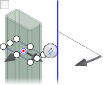
- Use the display controls to set the zoom and view orientation.
- Sets the view perpendicular to the frame manipulators.
- Zooms to the frame manipulators.
- Returns the display to the initial view.
- Optionally click Align selection and then click a linear edge, planar face, work axis, work plane, or sketch line to orient the member.
- Click Apply and then click OK in each dialog box to accept.
- Continue to modify frame members as needed, and then click OK when you are finished.
Visit the Tutorial Gallery for frame generator tutorials.