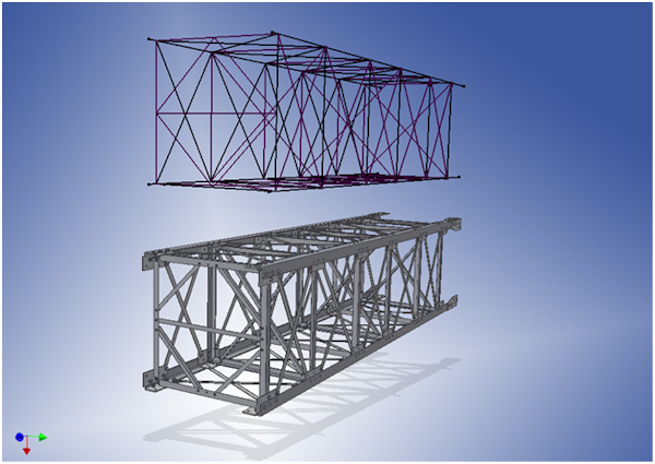
In the skeletal modeling method, you put all known factors into a skeleton file. Then you use it as a base for most of the subassemblies and parts that make up the assembly.

The skeletal modeling method can be used whether you are in Express mode or Full mode when working on an assembly.
A skeleton file can contain any type of element in any combination. The following is typical information created in a skeleton file:
- Sketches Define the concept of the final product, or use as a layout of different areas of the assembly.
- Work geometry Defines important connection points, axial directions, and work planes that define assembly levels.
- Parameters Define important values for part size, angles for placements, and other known values for the design.
- Solids Define volumes for final assembly as a single part or for defining subareas of the design.
Advantages
- Simple assembly or component creation.
- Easy design modification.
- Reference common connections or critical locations from a single file.
- You can be in Express Mode and use skeletal modeling. This method is particularly helpful with large assembly models.
Disadvantages
- Slight data volume increase.
- Additional creation of skeleton sketches.
Inventor commands that are commonly used with skeletal modeling
- Sketch blocks
- Sketch constraints
- Make Part
- Make Components
- Derive
- Adaptivity