Specifies adaptivity, inclusion or exclusion of document history, 3D snap spacing for the active part, and setting for tapped holes.
Access
Ribbon:
Tools tab
 Options panel
Document Settings
Options panel
Document Settings
![]() . In the dialog box, click the Modeling tab .
. In the dialog box, click the Modeling tab .
The active document type determines the available options.
Adaptively used in assembly
Available only when the active part is adaptive. Removes the indicator that a part is used adaptively in an assembly. Clear the check box to remove the adaptive indicator.
Compact Model History
Select to purge rollback document history when you save the file. Clear the check box to regenerate the document history to re-enable fast editing performance. Select Manage tab Update panel Rebuild All.
Advanced Feature Validation
Sets the algorithm for computing part features.
When selected, uses a comprehensive compute algorithm that is slower but, can produce more accurate feature results in rare cases. Clear the option to use an optimized feature compute algorithm that significantly improves the performance of Shell, Draft, Thicken, and Offset features.
- To avoid unexpected topological changes, you cannot use a mixture of the two algorithms in one part.
- The Advanced Feature Validation option is not available for legacy parts that the comprehensive algorithm computes.
Maintain Enhanced Graphics Detail
When selected, saves graphics information with the file on disk. Uses this detail in the graphics display if the Application Options Settings - Display tab is set to Smoother.
Show Constraint State in Browser
Constraint status displays by default in the assembly browser as a
 ,
,
 , or
, or
 to indicate one of three states:
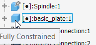
- Fully constrained A black dot indicates the component is fully constrained.
-
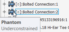
Under constrained A hollow dot indicates the component is under constrained and needs attention. To resolve, start by opening the Edit Constraint dialog box to identify possible issues.
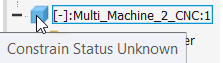
- Unknown A dash indicates the constrained status of the component is unknown. To resolve this state, rebuild the assembly: On the ribbon: Tools tab Manage tab Update panel Rebuild All
 .
.
Sectioning
- Participate in Assembly and Drawing Sections
-
When selected, in the component context menu in the drawing, the Section option is selected. The component participates in sections of Assembly models. When cleared, in component context menu in the drawing, the None option is selected. The component does not participate in sections of Assembly models.
Tapped Hole Diameter
Controls the model feature size of tapped holes according to the Major, Minor, Pitch, or Tap Drill diameter of the specified thread.
- Apply to legacy tapped holes
-
Updates the setting of existing legacy holes. When you select this option and click OK, all legacy tapped hole features that exist in the document assume the Tapped Hole Diameter setting.
3D Snap Spacing
Sets the spacing between snap points to help with precision when 3D sketching in the active part. Controls snap precision when using Move Feature to drag a feature.
User Coordinate System
Click Settings: To open the UCS Settings dialog box . Set the UCS naming prefix, define the default plane, and select the visibility of UCS and its features.
Initial View Extents
On file creation, sets the initial visible area when creating a model from a template. Configure this setting in your template files to affect new files. You can set the initial height and width of the graphics window.
The units for the Initial View Extents follow the setting on the Units tab for the template.
When you open an assembly in Inventor, , the active design view controls the initial view.
When you open a part file, the size of the part controls the initial view.
Naming prefixing
Controls the default naming scheme prefix for new solid or surface bodies. The default prefixes are Solid for solid bodies and Srf for surface bodies.
Make Components Dialog Box
Click Options to open the Make Components Options dialog box, with settings that are specific to the active project. You can establish different settings for each of your projects.
Repair Environment
When selected, automatically checks the model for quality after a manual repair operation, such as a boundary patch. Degrades performance when you select it on complex models.
Interactive Contact
The information in this section is applicable to assemblies only.
When selected, analyzes for contact between components. Degrades performance. Default is not selected.
- Contact Set Only
-
Limits the components considered for contact and collision in contact analysis to selected components. Then you can scale down the input to the contact solver.
Right-click in the assembly to specify the selected components as a contact set.
- All Components
-
Analyzes all components in the assembly for contact.
- Contact Solver Off
-
Turns off solver analysis.
- Surface Complexity
-
When selected, provides better performance at the cost of slightly less accurate contact and collision detection. Ignores complex surfaces that are within close proximity to each other.
-
All Surfaces
Considers all surfaces. Provides the most accuracy, but can be slow for some models.
-
General Surfaces
Takes into account most surfaces; ignores some fillets (blends). Eliminates the most problematic cases in terms of performance. Provides a reasonable compromise between performance and accuracy.
-
Simple Surfaces
Ignores non-analytic surfaces. Yields the best performance, but misses any contact between nurbs surfaces.
-