The main properties of bush or roller chain as well as sprockets are described here. The short pitch chains as well as double pitch chains are considered. The chains can have single or multiple strands. All properties are defined within a library of chains.
Roller chain properties
Main chain properties are based on national standard recommendations. Specific size of the chain also defines corresponding dimensions for tooth sprockets as they have to engage properly with the chain.
|
|
where: |
|
|
p |
pitch |
|
|
p t |
transverse pitch |
|
|
b |
maximum width over bearing pins |
|
|
b 1 |
minimum width between inner plates |
|
|
d 1 |
maximum roller diameter |
|
|
d 2 |
maximum bearing pin body diameter |
|
|
t 1 |
thickness of inner plates |
|
|
t 2 |
thickness of outer plates |
|
|
h 2 |
maximum inner plate depth |
|
|
h 3 |
maximum outer or intermediate plate depth |
|

Toothed sprocket properties
Sprocket dimensional properties are based on a specific chain size as well as national standard recommendations. Not all properties are described here because of complexity. For more details on exact sprocket dimensions see the corresponding chain standards.
Two types of tooth form are considered:
- Theoretical tooth form
- Simplified ISO tooth form
The theoretical tooth form is designed so that the chain rollers ride out towards the tips of the sprocket teeth as the chain wears and elongates. There are many ways how to produce sprocket teeth, and the actual tooth form may not exactly match the theoretical form.
Simplified ISO tooth form is determined by the minimum and maximum tooth gap forms. The actual tooth form, which is provided by cutting or an equivalent method, shall have tooth flanks of a form lying between maximum and minimum flank radii and blending smoothly with the roller seating curve subtending the respective angles. By default the Roller Chain Generator uses minimum tooth gap form recommendations.
|
|
|

|
|
||
|
|
||
|
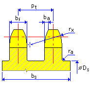
D f = D p - 2 r i |
||
|
b s = p t (k - 1) + b f |
||
|
b a = b ax p |
||
|
|
||
|
where: |

|
D P |
pitch diameter |
|
|
D a |
tip diameter |
|
|
D f |
root diameter |
|
|
d r |
maximum bush or roller diameter |
|
|
z |
number of sprocket teeth |
|
|
p |
chordal pitch equals to chain pitch |
|
|
p t |
strand transverse pitch |
|
|
k |
number of strands |
|
|
SC |
seating clearance |
|
|
r i |
roller seating radius |
|
|
r e |
tooth flank radius |
|
| α |
roller-seating angle |
|
|
h a |
height of tooth above pitch polygon |
|
|
b f |
tooth width |
|
|
b a |
tooth side relief |
|
|
b ax f |
tooth side relief factor |
|
|
r x |
tooth side radius |
|
|
r a |
shroud fillet radius |
|
|
b s |
minimum shroud width |
|
|
D s |
maximum shroud diameter |
|
|
h max |
maximum plate depth h max = max(h 2 ; h 3 ) |
Measuring toothed sprocket
|
Even number of teeth |
Odd number of teeth |
|
|
|
|
M r = D p + 2 D g - d r |
|
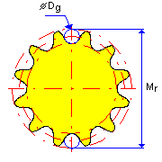
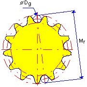
For measuring over pins D g = d r . For direct measuring D g =0.
where:
|
D P |
pitch diameter |
|
|
D g |
measuring pin diameter |
|
|
M r |
measurement over pins or direct measurement |
|
|
z |
number of sprocket teeth |
|
|
d r |
maximum chain roller diameter |
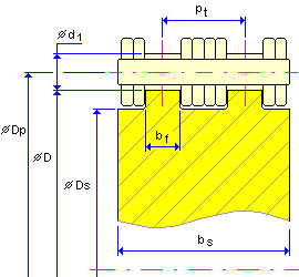
Flat idler
|
|
D p = D + d 1 |
|
|
b s = p t (k - 1) + b f |
||
|
|
||
where:
|
D P |
pitch diameter |
|
|
D |
nominal diameter |
|
|
p |
chain pitch |
|
|
p t |
strand transverse pitch |
|
|
k |
number of strands |
|
|
b f |
strand width |
|
|
d 1 |
maximum chain bush or roller diameter |
|
|
D s |
maximum shroud diameter |
|
|
b s |
minimum shroud width |
|
|
h max |
maximum plate depth h max = max (h2; h3) |