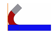
Defines a flange by adding a sheet metal face and a bend to an edge or edge loop on a face.
What's New: 2021
Unless you change the options for basic shape parameters, the flange is created with default settings for unfold, bend, and corner.
- Access
-
Ribbon:
Sheet Metal tab
 Create panel
Flange
Create panel
Flange

Shape tab
Specifies the edges, angle, radius, height, Datum from which height is measured, and Position of the bend relative to the edge.
- Edges
- Specifies one or more edges to which you apply the flange, or all edges defined by a loop of edges around a selected face.
- Edge
- Specifies one or more individual edges to which the flange is applied.
- Loop
- Specifies an edge loop and applies the flange to all edges of the selected loop.
- Flange Angle
- Value option: Defines the angle of the flange relative to the face containing the selected edges. The field accepts numeric entries, formulas, parameters, or measured values.
- By Reference option: Defines the angle of the flange to match the selected face or plane.
- Bend Radius
- Defines the radius of the bend between the flange and the face containing the selected edges. The value defaults to the system parameter named BendRadius, which is defined on the Sheet Metal Styles dialog box. The field accepts numeric entries, formulas, parameters, or measured values.
- Height Extents
- Specifies whether you define the height of your flange by a specific
Distance or by selecting
To geometry.
The To option uses the following method to calculate the termination.
- Distance gap
- Reference point
- Calculated distance
- Plane parallel to base plane
- Base plane
 For the height of the flange, enter a value and accept numeric entries, formulas, parameters, or measured values. Or, you can select geometry and later enter an offset value to allow the flange to be determined by the position of other geometry on the part.Tip: To enable dynamic drag of the height of the flange in the graphics window, click in the Height Extents Distance box.
- Flip Direction
 Available when the specified height is defined as Distance.
Note: Flip Direction uses the edge opposite from the selected edge while maintaining all other input flange parameters.The following illustration shows the results following selection of Flip Direction.
Available when the specified height is defined as Distance.
Note: Flip Direction uses the edge opposite from the selected edge while maintaining all other input flange parameters.The following illustration shows the results following selection of Flip Direction.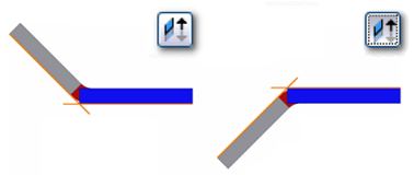
- Height Datum Options
-
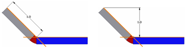
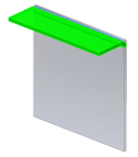
- From intersection of two outer faces

- Measures the flange height from the intersection of the outer faces. In the following illustration, the orange line indicates the outer faces.
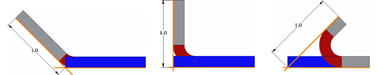
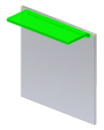
- From intersection of two inner faces

- Measures the flange height from the intersection of the inner faces. In the following illustration, the orange line indicates the inner faces.
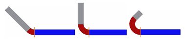
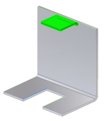
- From tangent plane

- Measures the flange height parallel to the flange face and tangent to the bend. In the following illustration, the orange line indicates the bend tangency line perpendicular to the flange face.
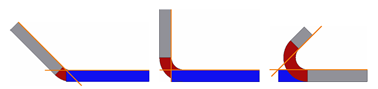
- Aligned/Orthogonal

- Specifies whether the height measurement is aligned with the flange face or orthogonal to the base face. Press the control to enable orthogonal mode. In the following illustration, the measurement on the left is aligned while the measurement on the right is orthogonal.
- Flange Angle Options
- Choose By Value to enter the angle value. Choose By Reference to select a planar face, planar surface, or an origin or work plane to match the angle to the selection.
- Bend Position Options
- Specifies where to position the bend relative to the extent of the face containing the selected edges or faces.
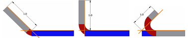
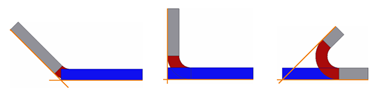
- Inside of reference plane

- Positions the outside face of the flange so that it remains inside of the face extents owned by the selected edge or face. In following illustration, the orange line indicates how the bend is positioned relative to the outside face and the selected edge.
- By Reference:
- Bend from Adjacent Face

- Starts the bend at the edge of the selected face. In the following illustration, the orange line indicates where the bend of the flange originates. Not available if Flange Angle is set to By Reference.
- Outside of reference plane

- Positions the inside face of the flange so that it remains outside of the face extents owned by the selected edge or face. In the following illustration, the orange line indicates the bend position relative to the inside face and the selected edge.
- By Reference:
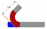
- Tangent to adjacent face

- Positions the bend tangent to the selected edge. In the illustration below, the orange line indicates the bend tangency condition relative to the selected edge. Not available if Flange Angle is set to By Reference.
- Inside of reference plane
- From intersection of two outer faces
 (More)
Specifies the extents of the flange.
- Edge
- Creates a flange the full length of the selected face edge.
- Width

- Creates a flange of a specified width at a specified offset from a single selected vertex, work point, work plane, or planar face on the edge of an existing face. You can specify that the flange is a specific width centered on the mid-point of the selected edge.
- Offset
- Creates a flange offset from two selected vertices, work points, work planes or planar faces on the edge of an existing face.
- From To
- Creates flange with the width defined by selecting existing part geometry (vertices, work points, work planes, or planar faces intersecting the defining edge) that defines the flange from and to extents.
- Old Method
- This option is unchecked by default in parts created with versions R2009 or newer. When checked, this option disables the new functionality which provides more control over the bend positioning and measurement. When editing flange features on sheet metal parts created with releases before R2009, this option is checked by default. You can edit the feature with the control that was active when the feature was created. Optionally, cancel this selection to obtain the full control provided in the current release.