The General Dimension command, as well as editing dimensions in place, is an editing command for controlling the linear, angular, and radial dimensions of manually defined sketched route points and segments. In addition, Autodesk Inventor Tube and Pipe provides a variety of commands for controlling distance in auto route regions and sketched route segments in rigid piping or bent tubing routes. Available commands include:
- Move Node, for intermediate route points that are associated with a default coupling fitting in an auto route region
- Edit Position, for both intermediate route points that are associated with a default coupling fitting and intermediate segments in an auto route region
- 3D Move/Rotate, for intermediate sketched route points and free terminal route points
- Edit Fitting Orientation, for placed fittings
Using these commands, you can make dynamic adjustments on route segments in a rigid route. For instance, you can position a placed tee, cross, or any other fitting precisely. Those commands typically give visual feedback on specific distances, but the tooltip definitions may vary.
- Before applying these commands, you can achieve a more accurate distance by controlling linear dimension precision. The default precision is 0.123. To change the current setting, click Tools tab
 Options panel
  Document Settings
  Units tab, and select an option from the Linear Dim Display Precision list.
 - To verify the distance, click Tools tab
 Measure panel
  Distance and select two points.
Move Node
The tooltip represents the relative distance between the position of the preceding route point and the target position of the route point being moved. The calculation is based on the direction the route was created.
The following exercise gives an example of a rigid piping route. It is assumed that the route was created from left to right.
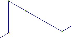
- Create a simple rigid route as shown in the following image.

-
 Use Route tab
  Create panel
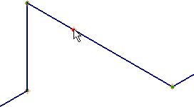
  Move Node and in the Model browser or graphics window, select a route point to move.
- Drag the cursor to move the route point back and forth along the segment.
Notice how the value in the tooltip represents the distance between the preceding route point and the target position, Point (1) and Point (3).

- Point (1): Preceding route point to Point 2
- Point (2): Route point to move
- Point (3): Target position of Point 2
- Point (4): Forward route point to Point 2
- Click to set the position.
Edit Position
The tooltip represents the relative distance between the original position and the target position of the route point being moved.
The following exercise gives an example of a rigid piping route.
- Create a simple rigid route as shown in the following image.

-
 In the Model browser or the graphics window, right-click the route point and select Edit Position.
 - Move the cursor along the red axis.
Notice how the value shown in the tooltip represents the distance between the original position and the target position, Point (2) and Point (3).

- Point (1): Preceding route point to Point 2
- Point (2): Route point to move
- Point (3): Target position of Point 2
- Point (4): Forward route point to Point 2
- Right-click and select Done.
- Right-click and select Enter Distance to set a value.
- Move your cursor over the direction axis, and then directly type a distance value on your keyboard when the green preview route point displays. The Enter Distance dialog box automatically prompts and displays the value. Press Enter to set the position.
Edit Fitting Orientation
It is available on the context menu of a placed fitting when the run is active. The tooltip represents the relative distance between the closest route point in the moving direction and the target position of the route point associated with the fitting. The route creation direction does not affect the tooltip in this case.
The following exercise gives an example of a bent tubing route.
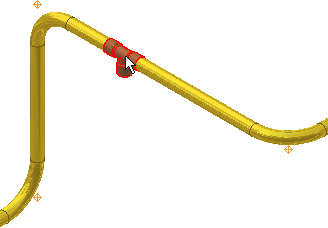
- Select a fitting to edit the position.

- Right-click the fitting and select Edit Fitting Orientation.
- Move the cursor along the red axis in the direction as shown in the following image.
Notice how the tooltip shows the relative distance from the target position to the closest route point in the direction of the moving cursor, Point (3) and Point (4).

- Point (1): Preceding route point to the tee fitting on Point 2
- Point (2): Tee fitting to move
- Point (3): Target position of the tee fitting
- Point (4): Forward route point to the tee fitting, closest route point in the direction of moving cursor
- Click to set the fitting position.
- To compare, move the repositioned fitting in the opposite direction.
Notice how the tooltip shows the relative distance from the target position to the closest route point in the direction of the moving cursor, Point (5) and Point (1).

- Point (1): Forward route point to the tee fitting, closet route point in the direction of moving cursor
- Point (3): Tee fitting to move
- Point (4): Preceding route point to the tee fitting on Point 2
- Point (5): Target position of the tee fitting
- Click to set the fitting position.
- Right-click and select Enter Distance to set a value.
- Move your cursor over the direction axis, and then directly type a distance value on your keyboard when the green preview route point displays. The Enter Distance dialog box automatically prompts and displays the value. Press Enter to set the position.
3D Move/Rotate
By default, the triad axes relate to the world coordinate system coherently but may vary from the route direction. To define the X, Y, Z distances relative to the route direction correctly, you can redefine the axis alignment to the route segment.
The distance you move the route point or the angle you rotate the route point is represented in the 3D Move/Rotate dialog box. The following exercise gives an example of a bent tubing route.
- Activate a bent tubing route.
- Right-click a manually placed route point or free endpoint, and select 3D Move/Rotate.
- Click the triad sphere and do not release the mouse, you can free drag the route point to a rough position. Do any of the following and enter an accurate value in the 3D Move/Rotate dialog box:
- To define an accurate move along an axis, click a triad axis arrow head.

- To define an accurate move in a plane, click a triad plane.

- To define an accurate unrestricted move, click the triad sphere.

- To define an accurate angle around an axis, click a triad axis segment (not arrow head).
 Note: Using free drag, it is difficult to get an accurate position as the triad segment value boxes are grayed out. For more information about 3D Move/Rotate, see Working with the 3D Move/Rotate command.
 - To define an accurate move along an axis, click a triad axis arrow head.