A route is a defined path with a specified style and is routed through assembly model geometry. It connects at least two route points within the context of an assembly. When routes and runs are populated, a series of continuous conduit parts and fittings are automatically generated from the Content Center at the defined path and style criteria are applied. If the style is a butt weld style, gaps may be displayed at the groove weld locations.
Tube and pipe styles define the industry standard, material, nominal diameters, minimum and maximum segment lengths, minimum bend radius, and other attributes. Each route can only use one tube and pipe style. A run can have one or more tube and pipe styles that are used for multiple routes. Routes can switch to another active style except between rigid routes and hose routes. Available tube and pipe styles include:
Rigid piping: One type of rigid routes
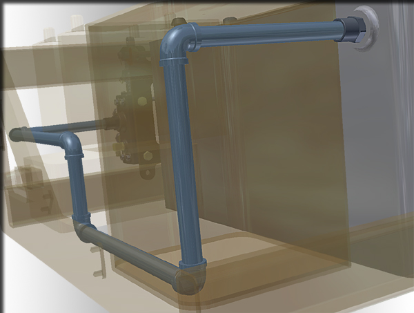
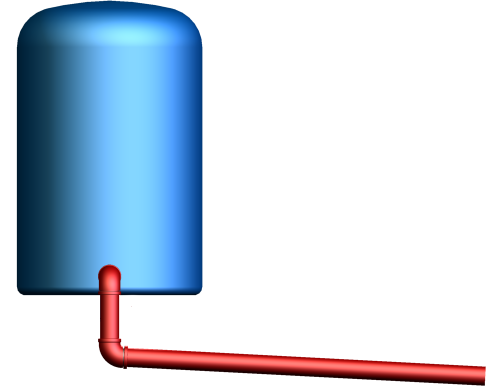
Rigid piping Self Draining Line: Another type of rigid routes
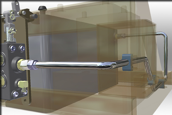
Bent tubing: One type of rigid routes
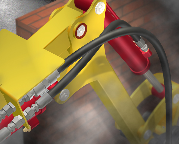
Flexible hosing
Depending on the route creation mechanism, a route can be categorized into the following route types:
- Auto routes. Note that an auto route region can be converted to sketched route segments using the Convert to Sketch command.
- Sketched routes
- Derived routes
A rigid route typically comprises a mixed set of auto route regions and sketched route segments. The rigid route types have many similarities, including the commands used to create and edit them. However, different commands are provided to create and edit flexible hose. Some elements are common among different types of routes. Some commands are unique to a particular route type.
What is the typical tube and pipe design workflow?
In tube and pipe design, you can add individual runs and routes in primary runs assembly and populate routes and runs using library parts conforming to tube and pipe styles. To reuse existing exclusive tube and pipe components, place secondary occurrences and follow the reuse workflow. Similar to Inventor assemblies, you can then create presentations, representations, and drawing documents for tube and pipe assemblies.
If you want to create a tube and pipe iAssembly factory, use the Make Adaptive command to make as many unique primary runs assemblies as you need. In the tube and pipe interchangeability set , each primary runs assembly member will work independently and can swap in for configuration. It can be reused in any number of configurations, but will only be adaptive in and hence respond to changes to one configuration.
The following is a general workflow for designing a typical tube and pipe assembly:
- Set up the project environment for your tube and pipe design, such as project type, location, styles library permission, and especially Content Center.
- Optionally, customize your own tube and pipe runs assembly template.
- Within a normal Inventor assembly, create a primary runs assembly.
- Specify rigid piping, bent tubing, and flexible hosing styles for route creation. Tube and pipe styles can also be created upon adding a new run or route.
- Add individual runs and routes as you need, such as rigid piping routes, bent tubing routes, flexible hosing routes, and derived routes.
- Populate routes and optionally set your own conduit part file names.
- Optionally, to reuse primary runs assembly, runs, routes, or flexible hose assemblies, place secondary occurrences and use the Make Adaptive command to transition them to new primary occurrences.
- Edit routes and runs.
- Create design view representations.
- Create positional representations and edit specific runs.
- Create model state representations.
- Create drawing views based on specific representation and configuration, create and export bill of material tables for routes and runs, and annotate drawings using parts lists, piping styles, and so on.
- Create tube and pipe presentations.
How are multiple routes added?
To create multiple routes in a run, you create the run, select an active style, and then create and define a route. Once the route is defined and edited, you either populate the route or drop a fitting on to the route to use as the start point for the next route. Continue dropping fittings and creating routes until the design is complete.
How do routes and runs respond to assembly changes?
Valid route edits only take effect when the resultant route conforms to style criteria. Unless tube and pipe defer updates is enabled, modifying a populated route updates the associated run once you exit the route environment.
|
Rigid routes |
In rigid piping and bent tubing routes, system automatically closes gaps left by deleted route points or couplings between straight segments. Segments adjoining the deleted route points reposition or resize to adjust to the change. Deleting a fitting occurrence on a route, automatically merges the adjacent pipes. Deleting a segment on a route removes the adjacent fittings similar to deleting a sketch line in route edit environment. In addition, auto route regions and sketched route segments respond to assembly changes differently:
|
|
Flexible hoses |
Hose routes are controlled by the start and end route point, and optionally intermediate route points. System automatically recalculates the hose length and adjusts the route when edits are made. |
|
Derived routes |
Derived routes are created from base sketches that are prepared on existing geometry. Normal edits cannot be directly made until you break the link in between, but changes to base sketches automatically update derived routes. |
How does existing geometry assist in route design?
In the tube and pipe assembly, if existing geometry such as vertex, linear geometry, planar face, and work features including work point, work axis, and work plane can help navigate through the route system, include them as reference geometry and apply appropriate geometric constraints and dimension constraints to define the design.
A route typically starts and terminates on certain valid geometry. Consequently, reference geometry will be automatically created and grouped into the Included Geometry folder, for instance, a work point is typically derived from selecting a circular edge and remain coincident with its center point. When route geometry including route points and segments are deleted, the underlying reference geometry remains.